


19
18
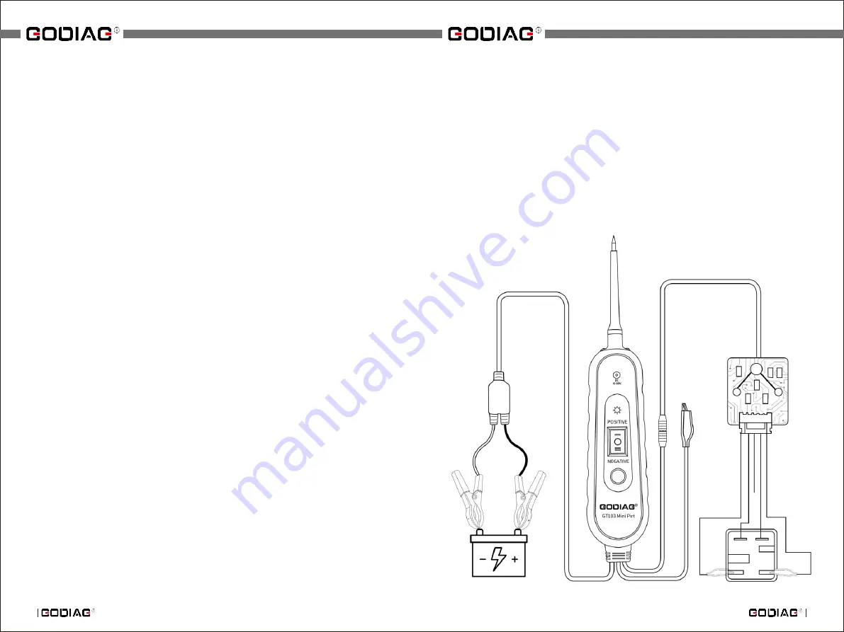
7.
)
Relay Test
Three Kinds of Relay Connection
1
)
Conventional Relays
Relay port 86, Positive power supply (red), 85 power supply negative
(black), 30 COM (yellow), 87 Normally Open (green),87a Normally Closed
(blue)
2
)
Special Relays
Relay port 1. Negative power supply (black), 2. Positive power supply
(red),3. COM (yellow), 4. Normally Closed (blue), 5. Normally Open (green)
3
)
Other Relays(port definition is not specific)
Users define the connection according to the port of the relay.
Relay Test Procedures
1.Prepare relay test leads and connection adapters.
2.According to the characteristics of the relay, customers can distinguish,
the coil end of the relay, the common end, the normally open end and the
normally closed end. Connect the relay.
3.Connect the black battery clip of Godiag GT103 Mini Pirt Electric Circuit
Tester to the negative electrode of the battery and the red battery clip to the
positive electrode of the battery. If the Godiag GT103 Mini Pirt Electric Circuit
Tester displays normally, and the illumination LED lights it means that the power
supply of the equipment is normal.
4.Press the function button of the fuel injector relay and the buzzer will beep
once. Function output green light flashes .
5.The relay test signal is transmitted to the relay test line and the relay
adapter to drive the relay to work.
Result Judgment:
A.For relays with normally open and normally closed functions, the red
power light on the relay adapter flashes; for the normally open, green light
flashes; for the normally closed, the blue light flashes.
B
.
For relays with only normally open function, the red power light on the
relay adapter flashes; for the normally open, the green light flashes; for the
normally closed, the blue light goes out.


