II. Installation
1.
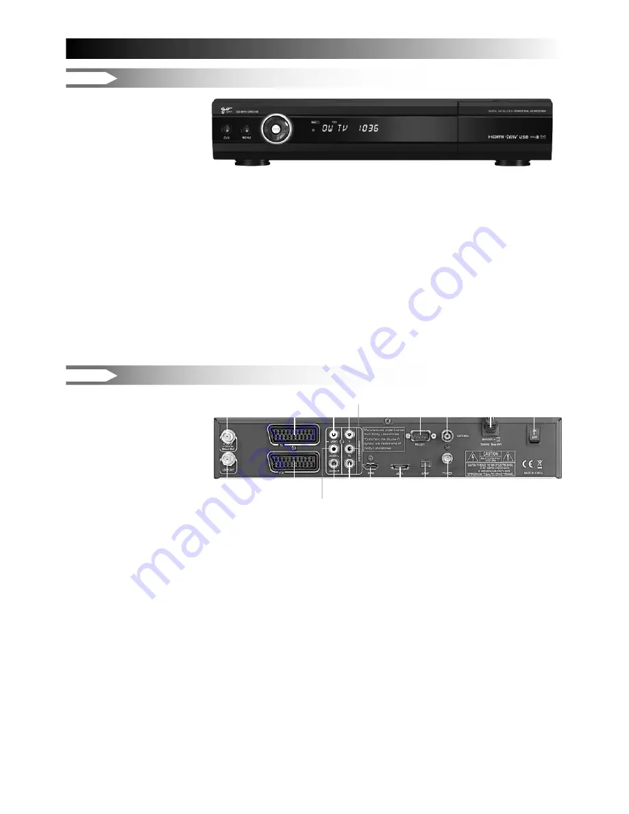
Front
Panel
•
POWER:
To put Power in and out of standby mode
• CHANNEL
▲
/
▼
:
To move up and down in the menus, To change channels
• VOLUME
◄
/
►
:
To make volume up/down & to change the value of a selected line
•
EXIT:
To exit from Menu mode
•
MENU:
To enter main menu screen
•
OK:
The OK button is used to select sub menu and con
fi
rm selection or to watch channel list
•
DISPLAY:
To show channel number, resolution, remote control commands or show current time
in standby mode
•
RESOLUTION MARK:
To show a resolution
•
USB:
Connect to USB memory storage device and upgrade software of STB
•
CAS SLOT:
Insert Smart Card (CAS model only)
•
CAM SLOT:
Insert CAM (Common Interface : slot 1 / slot 2) for Smart Card (CI model only)
NOTE!
Front could be changed according to the model & option.
2.
Rear
Panel
1. IF INPUT:
IF INPUT from LNB to receiver
2. IF OUTPUT:
IF Loop-through output to 2nd receiver
3. TV SCART:
TV Scart output
4. VCR SCART:
VCR Scart output
5. VIDEO:
Composite Video Output
6. AUDIO L:
Left Audio Output
7. AUDIO R:
Right Audio Output
8. Y:
Component Video Output
9. Pb:
Component Video Output
10. Pr:
Component Video Output
11. HDMI:
To connect to TV with HDMI cable
12. S/PDIF:
For Digital Audio Output
13. ANTENNA:
To connect to terrestrial antenna input (DVB-T: option)
14. TV/VCR:
RF loop through output to 2nd receiver (DVB-T: option)
15. POWER SUPPLY:
AC 90-240V, 50/60HZ
16. AC SWITCH:
AC Power ON/OFF
17. E SATA:
To connect to to external HDD with SATA cable (option)
18. RS-232C DATA PORT:
To connect with PC
NOTE!
Rear image could be changed according to the model type & option.
5
1
3
5
8 9
18
13
15
16
2
4
6 7
10
11
17
12
14
Содержание GS 8010
Страница 1: ...USER S MANUAL GS 8010...


