background image

PA G E   8  

i n s t r u c t i o n   m A n uA l  

G r 9 2 0 0   s E r i E s

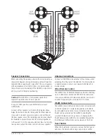
Yellow

Red

0.5 AMP

Memory

Ignition Switch or 
external AUX Switch

Optional 
Master 
Switch

ElECTRICAl WIRING

dc connections

Caution:

 the Gr9200 is designed for vessels with a 12 Volt 

negative ground electrical system only!

Referring to the wiring diagram on this page:

1.  Connect the YELLOW wire directly to the positive 

terminal of the vessel’s battery, or to a point that has 
+12 Volts available at all times. This lead maintains the 

memories within the Gr9200 and is the main power 
source for the unit .

2 .  connect the rED 

wire to the v12 V supply via 

an appropriate isolating switch or circuit breaker. This 
lead enables the radio to be switched ON and OFF. 
Alternatively, this wire can be connected directly to the 
battery’s positive terminal and the GR9200 switched ON 

and oFF using it’s own controls .

3 .  connect the 

BLACK wire to the battery’s negative 

terminal 

or to the common negative bus in the electrical system.

important:

 Your GR9200 is able to maintain it’s memories 

when it is switched off by drawing power directly from 
your battery via the Y

ElloW

 ‘Memory’ lead. Although 

the memory backup current is very small (about 10 mA) 
it may eventually discharge your battery if left connected 
indefinitely. The time taken to completely discharge your 
battery could vary depending on its Amp-hour rating and 
battery condition.

If you do not run your boat’s motor regularly or your battery 
is not kept charged between outings (e.g. Solar or wind 
charger), we recommend you disconnect the Y

ElloW lead 

each time you secure or trail your boat. This is easily done 
by connecting the Y

ElloW

 ‘Memory ’ lead via a Master 

switch, which can be switched off after each outing. This 
will mean you will loose all your preset station memories 

and clock settings .

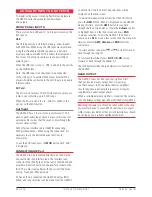
The blue wire on the wiring loom supplies 12 Volts when 
the GR9200 is switched on and can be used to turn on an 
external device, like the GME GA9800 marine amplifier, or 
enable the back light on the GME RCU9200 wired remote.

Содержание GR9220B

Страница 1: ...GR9200 S E R I E S I N S T R U C T I O N M A N U A L MARINE STEREO SYSTEMS GR9220W GR9220B GR9240W GR9240B...

Страница 2: ...peration 10 CD MP3 operation 11 Configuration mENU TABLE 13 AUXILIARY INPUTS OUTPUTS 14 Front Panel Inputs 14 Aux Input 14 Rear Output 14 OPTIONAL ACCESSORIES 15 GR9200 Trouble Shooting Guide 16 speci...

Страница 3: ...come the standard by which all marine stereo systems are measured Please read this instruction booklet carefully drop in your favourite music selection sit back and enjoy the sounds that cannot fail t...

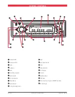
Страница 4: ...Control 3 Select 4 Loudness 5 Mute 6 Clock Time Selector 7 Mode Switch 8 LOC DX Selector 9 Stereo Mono 10 Band Selector 11 Tuning Selecting Tracks 12 Eject 13 Auto Music Search 14 Scan 15 Release But...

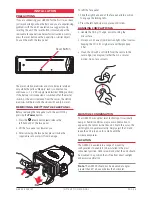
Страница 5: ...ace panel place it inside the supplied case to protect it from damage To refit the face panel 1 Slide the right hand end of the face panel into position to engage the locking tabs 2 Press the left han...

Страница 6: ...ly mark the location of the bracket edges Now remove the unit from the bracket and reposition the bracket at the desired location to mark the mounting hole positions 3 Screw or bolt the bracket into p...

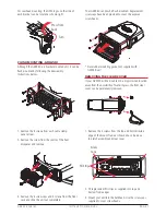
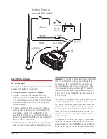
Страница 7: ...t out completely Your GR9240 can now be flush mounted Replacement screw caps have been provided to cover the exposed screw heads Removing the Clear Cover If your GR9200 will be mounted in a dry protec...

Страница 8: ...nal or to the common negative bus in the electrical system Important Your GR9200 is able to maintain it s memories when it is switched off by drawing power directly from your battery via the Yellow Me...

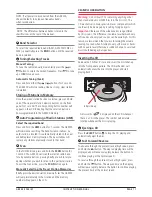
Страница 9: ...s should be insulated to ensure they cannot short circuit together or to the vessel s 12 Volt or negative electrical Bus If using only two speakers adjust the Fader control to the rear speakers Antenn...

Страница 10: ...to indicate the GR9200 has been muted Pressing the MUT button again will restore the previously selected audio level 6 Clock To display the current time press the button After 2 seconds the display w...

Страница 11: ...listen to this particular station To exit the Scan mode press the Scan button again Manually Selecting the Preset Station Memories Briefly press the desired station memory 1 6 The GR9200 will jump im...

Страница 12: ...mits a large number of files to be stored on a CD R CD RW SD Card or USB memory stick MP3 Music Search To search for a particular MP3 music track press the AMS button once the LCD will display TRK The...

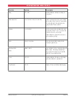
Страница 13: ...sed when the radio is turned on Select Last to restore the volume to the last used setting Select Default to restore the volume to a present default setting AVOL Min 01 46 Max Sets the preset volume s...

Страница 14: ...LE023 iPod interface lead The interface lead connects to the iPod fly lead at the rear of the GR9200 and provides a direct connection to the interface socket on the iPod The cable is compatible with...

Страница 15: ...rs Comprehensive Range of Marine Antennas Interface cable for MP3 devices RCU9200 Wired Remote Control for Stereo LE024 Wired Remote 5m Extension Cable LE023 iPod Connectivity Lead 1 1m Long iPod is a...

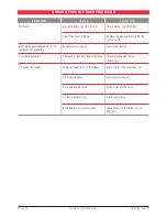
Страница 16: ...on LCD or functions not operating Microprocessor lock up Press Reset Button Poor radio reception Damaged or incorrect type of antenna Check antenna and replace if necessary CD cannot be loaded There...

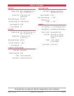
Страница 17: ...ies 12 Compact disc mechanism Mechanism Auto Loading Signal to Noise Ratio 58 dB Format 8 times oversampling Environmental Anti vibration Anti shock audio amplifier Audio Output 4 channels x 45 W Peak...

Страница 18: ...period of warranty for the goods into which they are incorporated 2 3 We warrant our other repairs to be free from defects in materials and workmanship for three months from the date of the original...

Страница 19: ...GR9200 series instruction manual PAGE 19...

Страница 20: ...24 College Street East Tamaki Tel 03 9798 0988 THEBARTON 5031 CANNING VALE 6155 OXLEY 4075 GLADESVILLE 2111 MANUKAU 2013 NZ Fax 03 9798 0177 Tel 08 8234 2633 Tel 08 9455 5744 Tel 07 3278 6444 Tel 02 9...

Отзывы: