background image

PRECAUTIONS OF USING

SAFELY

Pay special attention to the safety at the parts of this manual that
are indicated by the following marks

.

Observe the following precautions to ensure use in security

:

MEANINGS OF SPECIAL MARKS

DANGER

MEANING

MARK

WARNING

CAUTION

If not carried out properly

procedures

which may lead to dangerous condition
and cause death or serious injury to the
user

,

.

If not carried out properly

procedures

,

which may lead to dangerous condition
and cause death or serious injury to the
u s e r

O r

p r o c e d u r e s

w h e r e

t h e

probability of superficial injury or physical
damage is high

.

.

If not carried out properly

procedures

,

where the possibility of serious injury to
the user is small

but there is a danger

of injury or physical damage

,

.

Prohibited

Mandatory

SYMBOL

:

1

10

ADJUSTMENTS BEFORE

FLYING

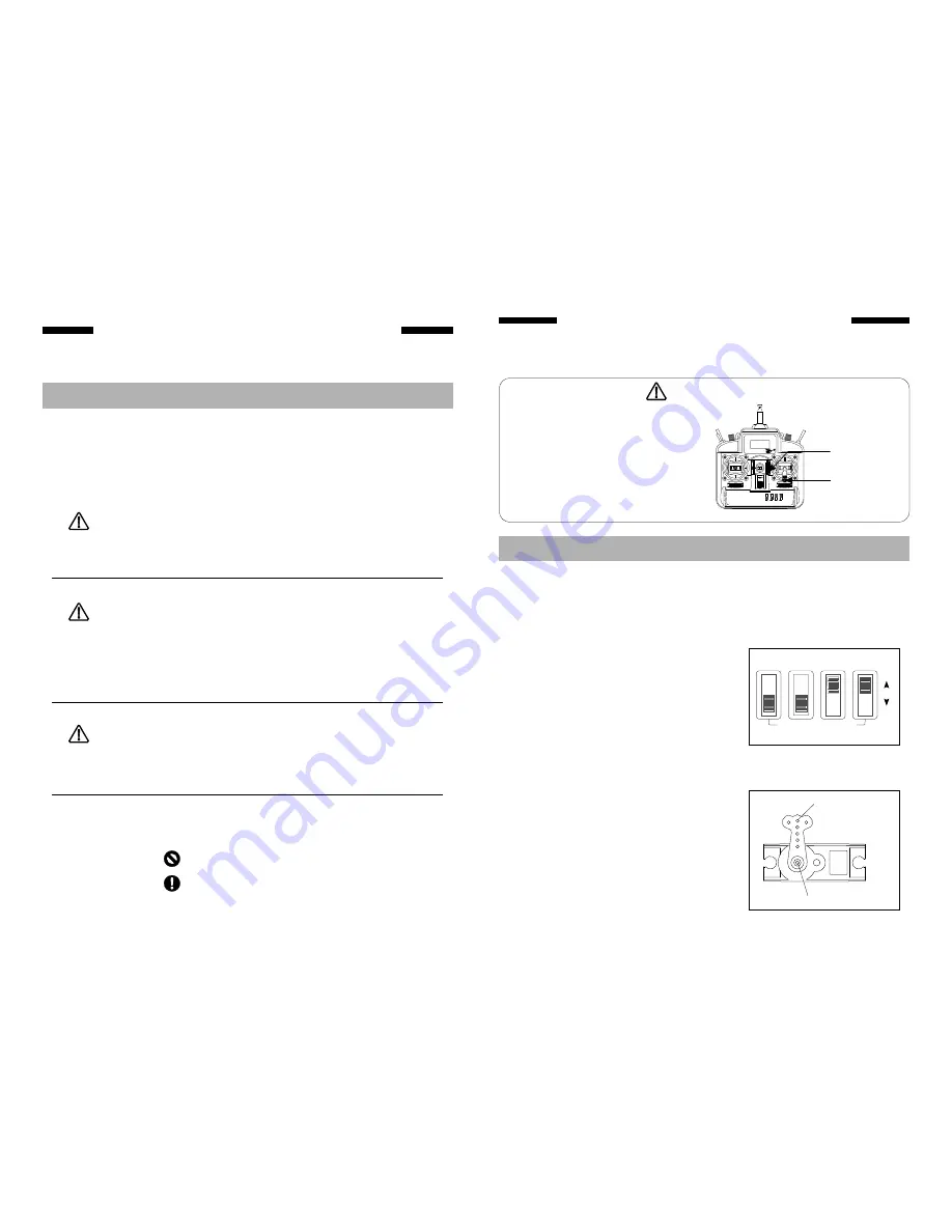
The operating direction neutral position

and steering angle of

each servo are adjusted

,

,

.

CAUTION

ADJUSTMENT PROCEDURE

Before making any adjustments set all the SERVO REVERSER
switches on the front of the transmitter to the lower NOR

position

Turn on the transmitter and receiver power switch then make the
following adjustments

,

(

)

.

,

:

1 Check the direction of operation of each servo

.

.

2 Check the aileron, elevator, and rudder neutral adjustment

and left-right (up-down) throw.

.

Check that when trimmed to the center,
the servo horn is perpendicular to the
servo and check the neutral position of
the fuselage control surfaces ( aileron,
elevator, rudder , etc.). If the neutral
p o s i t i o n h a s c h a n g e d , r e s e t i t b y
adjusting the length of the rod with the
linkage rod adjuster.

SERVO REVERSER

AIL

ELE

THR

RUD

REV

NOR

Perpendicular

Rod

If

a

servo

operates

in

the

wrong

d i r e c t i o n

s w i t c h

i t s

S E R V O

REVERSER switch

The direction of

operation

can

be

changed

without

changing the linkage

Note

that

the

direction

of

the

aileron servo is made easily mistakes

,

.(

.)

*

.

The software of this transmitter has the
function of autocorrect to center position, so
before turning on the power switch of the
transmitter, make the following adjustments:

1

Set the Throttle Stick and Throttle

Trim Lever to the lowest position

2

Set the Elevator Trim Lever

Rudder

Trim Lever and Aileron Trim Lever to the
middle position

and insure their stick to

the center position

.

.

.

,

,

.

Throttle trim lever

Mode 1

(

)

Throttle stick

Mode 1

(

)

ON

L C D V O LTA G E I N D I C AT O R

Содержание JFT602

Страница 1: ...D P R C S IGITAL ROPORTIONAL ADIO ONTROL YSTEM R www gm fly com GM FLY www gm fly com R JFT602 CCPM FM INSTRUCTION MANUAL SIX CHANNELS ...

Страница 2: ...tlet 1 Connect the charger connector to the transmitter charging jack 2 Connect the charger to an 110V AC outlet 3 A t t h e e n d o f c h a r g i n g disconnect the charger from the AC outlet CHARGING THE Ni Cd BATTERY To transmitter charging jack Ni Cd battery system only Charger 12 ...

Страница 3: ...ach servo 4 After all the linkages have been connected recheck the operating direction throw etc The stick spring strength can be adjusted The operating feel of the aileron elevator and rudder sticks can be individually adjusted STICK LEVER SPRING TENSION ADJUSTMENT 1 Remove the six transmitter rear case screws and remove the rear case 2 Adjust the spring strength by turning the screw of the chann...

Страница 4: ...nsmitter and receiver power switch then make the following adjustments 1 Check the direction of operation of each servo 2 Check the aileron elevator and rudder neutral adjustment and left right up down throw Check that when trimmed to the center the servo horn is perpendicular to the servo and check the neutral position of the fuselage control surfaces aileron elevator rudder etc If the neutral po...

Страница 5: ... other or damage of houses Do not fly when you are tired sick or drunken The mini helicopter may cause a crash due to the shortage of your attention or incorrect judgment 2 ON L C D V O LTA G E I N D I C ATO R ON L C D V O LTA G E I N D I C ATO R ON L C D V O LTA G E I N D I C ATO R Pitch servo Aileron servo Gyro ESC Elevator servo Battery pack Pitch servo Gyro ESC Elevator servo Aileron servo 9 B...

Страница 6: ...and for a short time after flying It may cause scald easily due to high temperature 3 ON L C D V O LTA G E I N D I C ATO R ON L C D V O LTA G E I N D I C ATO R RECEIVER Crystal The crystal is replaced from the side of the receiver Output battery connector B Battery connector 6 Pitch servo CH6 5 CH5 4 CH4 3 Throttle servo CH3 2 Elevator servo CH2 1 Aileron servo CH1 no used Gyro Crystal Lead 8 B 6 ...

Страница 7: ...electrolyte leakage etc Charge the Ni C d b a t t e r y before flying T h e m i n i helicopter that out of battery will prang 4 B 6 5 4 3 2 1 ON L C D V O LTA G E I N D I C ATO R Switches that reverse the direction of operation of the servos The lower position is the normal side and the upper position is the reverse side C h a n n e l d i s p l a y A I L A i l e r o n C H 1 E L E E l e v a t o r C...

Страница 8: ...n then the battery cannot charge filled and the time of flying will decrease may cause a crash Prohibited Mandatory CAUTION If not remove the electrolyte leakage of the batteries will affect them performance and Remove the batteries from transmitter or helicopter if you will not use them for a long time Do not expose the battery to d i r e c t s u n l i g h t e x t r e m e temperature degrees Cels...

Страница 9: ...ipment has been tested and found to comply with the limits for a digital device pursuant to part 95 of the FCC Rules These limits are designed to provide reasonable protection against harmful interference in a residential installation This equipment generates uses and can radiate radio frequency energy and if not installed and used in accordance with the instructions may cause harmful interference...

Отзывы: