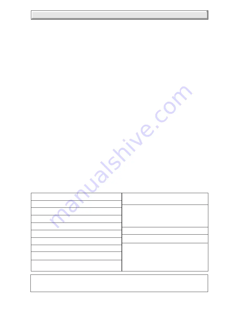
Glow-worm swift flow 75e Скачать руководство пользователя страница 3

3

221138C

D.H.W

0.5 to 10bar

working pressure

(7.25 to 188lbf/in

2

)

Maximum Heating

119 litres

system water

(26.2 gallons)

content using

with a cold

fitted expansion

fill pressure

vessel.

of 0.7bar

Electrical supply

230V~50Hz

Electrical rating

154W fused 3A

Internal Fuse rating

1) Type T2A
2) Type T630mA

Lift Weight

37.0kg (81.4lb)

Total Weight

50.4kg (111lb)

Gas connection

Rc

1

/

2

  (

1

/

2

in BSPT)

Heating and return

22mm compression

Domestic hot water

15mm compression

Safety valve

Preset 3bar (43.5lbf/in

2

)

Safety valve discharge

15mm copper

Water content

1.74 litres (0.38 gallon)

Expansion vessel capacity 8 litres (1.76 gallons)

Heating cold fill

0.7bar

pressure minimum

(10.1lbf/in

2

)

1   G e n e r a l

For larger systems use an additional expansion vessel, see Section 4.

Boiler starts at an inlet pressure of 0.5bar but requires 0.8bar for maximum output.

Ball valves are fitted in water and gas connections, plus a drain point on all water connections.

TABLE 2

1 General

The instructions consist of three parts, Installation,
Servicing and Instructions for Use, which includes the
Guarantee Registration Card.  The instructions are an
integral part of the appliance and must, to comply with
the current issue of the Gas Safety  (Installation and Use)
Regulations, be handed to the user on completion
of installation.

Testing and Certification

This boiler is tested and certificated for safety and
performance.  It is therefore important that no alteration
is made to the boiler, without permission, in writing,
from Hepworth Heating Ltd.

Any alteration not approved by Hepworth Heating Ltd.,
could invalidate the certification, boiler warranty and
may also infringe the current issue of the Statutory
Requirements, see Section 1.4.

CE Mark

This boiler meets the requirements of Statutory
Instrument No. 3083 The boiler (Efficiency)
Regulations, and therefore is deemed to meet the
requirements of Directive 92/42/EEC on the efficiency
requirements for new hot water boilers fired with liquid
or gaseous fuels.

Type test for purposes of Regulatioon 5 certified by:

Notified body 0087.

Product/production certified by:
                       Notified body 0087.

The CE mark on this appliance shows compliance with:

1. Directive 90/396/EEC on the approximation of the
laws of the Member States relating to appliances burning
gaseous fuels.

2. Directive 73/23/EEC on the harmonization of the
Laws of the Member States relating to the electrical
equipment designed for use within certain voltage limits.

3. Directive 89/336/EEC on the approximation of the
Laws of the Member States relating to
electromagnetic compatibility.

1.1 Installation

Materials and equipment should be fit for their purpose
and of suitable quality and workmanship.

1.2 Important Notice

This boiler is for use only on natural gas, G20.

1.3 Sheet Metal Parts

WARNING.  When installing or servicing this boiler
care should be taken when handling the edges of sheet
metal parts to avoid any possibility of personal injury.

1.4 Requirements

The installation of this boiler must be carried out by a
competent person in accordance with the rules in force in
the countries of destination.

Manufacturer’s instructions, supplied.

Manufacturer’s instructions must not be taken as
overriding statutory requirements.

1.5 Data Label

The data label is on the inner case cover.

1.6 Data

See tables 1 and 2

Содержание swift flow 75e

Страница 1: ...shire DE56 1JT General Sales enquiries Tel 01773 824141 Fax 01773 820569 One Contact Local Service Customer Services Tel 01773 828100 Fax 01773 828070 Installation Instructions To b e l e f t w i t h...

Страница 2: ...000 22 0 75 000 8 79 30000 15 6 6 3 8 0 3 4 2 4 1 0 2 0 69 5 2 6 92 5 1 2 42 1 C H MAX D H W MAX MIN NOMINAL kW HEAT INPUT NETT Btu h NOMINAL kW HEAT OUTPUT Btu h BURNER mbar PRESSURE in wg APPROX m3...

Страница 3: ...pworth Heating Ltd could invalidate the certification boiler warranty and may also infringe the current issue of the Statutory Requirements see Section 1 4 CE Mark This boiler meets the requirements o...

Страница 4: ...e used provided they are not used in a room containing a bath or shower The mains supply cable and other cables connected to the boiler must be the PVC flexible type of at least 0 75mm2 24 0 20mm 2 1...

Страница 5: ...used and can be supplied This is able to provide the duct length range shown in diagram 3 3 for rear flue or diagram 3 4 for a side flue A Flue Bend Kit or Vertical Flue Kit can be supplied with inst...

Страница 6: ...ACK Part No 438130 2 off 1 off 1 off MAX FLUE LENGTH X Y Z 600mm Diagram 3 5 230 MIN 194 MIN Part No 448468 1 off Part No 448491 FLUE KIT 1m 1 off Part No 448490 FLUE BEND KIT FLUE KIT 2m ELBOW TERMIN...

Страница 7: ...from Air Vent Internal space Outside 3 F l u e a n d V e n t i l a t i o n 3 4 Timber Frame Buildings If the boiler is to be installed in a timber frame building seek advice from the local gas undert...

Страница 8: ...RELATIVE SYSTEM DIFFERENTIAL AT VARIOUS SYSTEM HEATING LOADS M AVAILABLE PUMP HEAD SYSTEM DIFFERENTIAL TEMPERATURE SYSTEM HEATING LOAD 0 5 10 15 17 20 11 40 35 30 6 25 19 8 15 10 5 0 F 0 C 0 0 15 30 4...

Страница 9: ...the required system differential temperature axis to intersect the curve In the example 11 C 19 8 F has been chosen shown At the point of intersection draw a vertical line to cross the pump curve fro...

Страница 10: ...imum The bypass must have a lockable valve B in diagram 4 2 incorporated in a position so that inadvertent closure or unauthorised interference is not possible The bypass MUST be fitted before any sys...

Страница 11: ...diators then thoroughly cleaning out before fitting the boiler whether or not adding an inhibitor 4 11 Draining A draining tap must be provided at the lowest points of the system which will allow the...

Страница 12: ...flap Open the control door see diagram 6 1 Remove the two screws securing the outer case and then lift it at the top and pull it forwards and off Remove the cover of the inner case secured with four s...

Страница 13: ...internal corner where the flue is required to exit to outside Mark the position of the circular hole on the flue exit wall using the dimensions given in diagram 6 5 From the flue position marks check...

Страница 14: ...uitable see diagram 3 1 for a standard flue system or diagram 3 3 for a 1 2 or 3metre flue system For a side flue measure the distance from the outside wall face to the side of the boiler mounting fra...

Страница 15: ...orrect position and sticking out the correct distance from the outside wall face see diagram 7 1 and appropriate diagram 7 2 or 7 3 Drill a hole diameter as shown in diagram 7 4 in each side of the ai...

Страница 16: ...l clear the expansion vessels If necessary temporarily fit the boiler refer to Section 10 1 Mounting the Boiler Flush out the domestic water and heating system before connecting the boiler Make the co...

Страница 17: ...Controls CAUTION To prevent an induced current from switching the central heating on when not required it is important that the heating system control cables are separated from the other mains supply...

Страница 18: ...STAT 3 L N 2 1 3 AMP FUSE L N 230V 50Hz PERMANENT MAINS SUPPLY POTENTIAL FREE ROOM STAT NO FROST STAT TO BOILER RED LINK REMOVE WHEN CONNECTING SYSTEM CONTROLS 5 POLE CONNECTOR ON MOUNTING FRAME POTE...

Страница 19: ...boiler by tightening the two boiler securing screws at the top 10 4 Discharge Pipe Remove the two control housing securing screws see diagram 10 1 Remove the control housing and support the control h...

Страница 20: ...eve and the flue system should not be inserted unless the cement has fully set or it can be held from the other side Fit the flue elbow to the top of the boiler see diagram 10 6 using the four screws...

Страница 21: ...s in line with the length of the valve see diagram 8 1 Flush fill and vent the system refer to Section 4 9 Filling Sealed Systems WARNING SEVERAL COMPONENTS OPERATE ON MAINS VOLTAGE AND WITH THE OUTER...

Страница 22: ...DJUSTING NUT MIN PRESSURE 11 3 Preparation for Lighting Isolate the boiler from the mains electrical supply at the external isolator Test for soundness and purge air from the gas supply Turn on the ga...

Страница 23: ...ainer To achieve this flow rate a water pressure of at least 0 8bar is required during commissioning although subsequently the appliance will work at a minimum pressure of 0 5bar This flow rate should...

Страница 24: ...s 2 4mbar 0 2mbar 1 0in wg 0 1in wg for the 75e and 2 2mbar 0 2mbar 0 9inwg 0 1 in wg for the 80e If this is incorrect it may be adjusted by removing the cap and turning the larger adjusting nut of th...

Страница 25: ...e like are switched on programmed and calling for heat Set switch C to On as shown in diagram 11 1 The pump will circulate water through the boiler and the main burner will light Check that the burner...

Страница 26: ...ressure to the initial cold fill design pressure using the external draining tap close to the boiler refer Table 2 and Section 4 11 Lock or remove the handles from the spindles of flow control valve A...

Страница 27: ...ration of the appliance it is recommended that it is checked and serviced at regular intervals The frequency of servicing will depend upon the particular installation and usage but in general once a y...

Страница 28: ...C FIBRE GLASSYARN MINERAL WOOL These can cause irritation to skin eyes and the respiratory tract If you have a history of skin complaint you may be susceptible to irritation High dust levels are usual...

Отзывы: