


Supplied By www.heating spares.co Tel. 0161 620 6677
22
221473B
10 Boiler Fixing
Diagram 10.4
2833
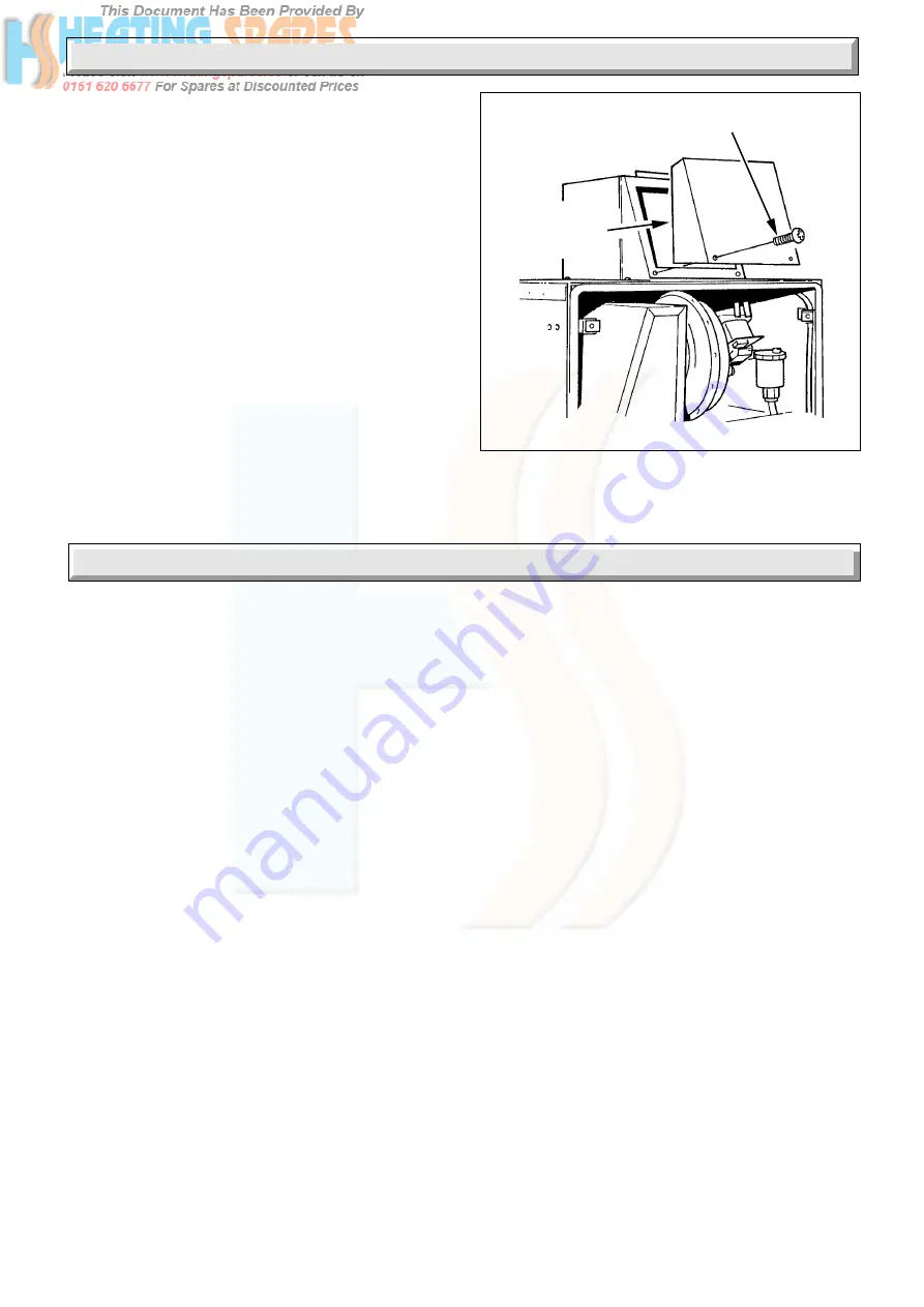
AIR BOX
ACCESS PLATE
AND GASKET
SECURING
SCREW
10.7 Flue Fixing
Remove the air box access plate from the front of the air box,
see diagram 10.4.
Pass the prepared air box and flue assembly into and through
the wall.
Place the air box gasket supplied in the loose items pack,
between the boiler top and airbox.
Loosely fit the air box to the boiler.
Using the air box access hole, fit the flue elbow onto the fan
outlet and secure with the flue elbow clip, see diagram 10.3.
MAKE SURE THAT THE FLUE DUCT REMAINS ENGAGED
IN THE TERMINAL.
Tighten the screws securing the air box to the top of the boiler
taking care not to damage the air box gasket.
Refit the air box access plate and gasket
Make sure that the ductings do not slope down towards the
boiler.
Make the wall good internally and externally around the air duct.
11.1 Filling Domestic Water Circuit
Check that the boiler is isolated from the electrical supply, at the
external isolator.
Fully open the domestic water supply stop cock or valve in the
supply to the boiler.
Open the two domestic water isolation valves, slots in line with
the length of the valve, see diagram 8.1.
Open all hot water draw-off taps and close them when the water
flows. Check for water soundness of the complete domestic
water system.
11.2 Filling the Heating Circuit
REMINDER: It is essential that a bypass is fitted in all
installations, refer to Section 4.7.
Open the two central heating isolating valves, slots in line with
the length of the valve, see diagram 8.1.
Flush, fill and vent the system refer to Section 4.9.
WARNING. Several components operate on mains voltage
and witH THE OUTER CASE REMOVED THEY BECOME
EXPOSED.
To assist in filling and venting, the pump may be used. Turn on
the electrical supply, if red lockout neon is lit press reset switch,
wait 15 seconds between attempts, set switch “C” to “ON” (see
diagram 11.1) any remote heating system controls, time switch
and room thermostat, for duty, see diagram 11.1.
Note. If the clock/timer kit is to be fitted, refer to the setting
instructions in the Instructions for Use.
Make sure that the automatic air vent is operating correctly, see
diagram 1.2.
Alternate the position of switch “C” between “ON” and “OFF” to
make sure that water flows through all parts of the boiler and air
is not trapped in the boiler internal bypass.
Pressurise the system until the pressure is 1.5bar (21.5lbf/in
2
),
pressure gauge “A”, see diagram 11.1.
Check the heating system and boiler for mwater soundness.
11.3 Preparation for Lighting
Isolate the boiler from the mains electrical supply at the external
isolator.
Test for soundness and purge air from the gas supply in
accordance with the rules in force in the countries of destination.
Turn on the gas service cock, slot in line with the length of the
cock.
Loosen the burner pressure test point screw and connect a
suitable pressure gauge, see diagram 11.2.
11.4 Burner Pressure - Hot Water
The burner pressure is factory preset and no adjustment should
be required.
Connect the electrical supply, the pump will operate for about 30
seconds, then the pump stops.
Fully open the largest hot water draw off tap whereby the main
burner will light, the flames gradually increasing to maximum.
Check the soundness of the boiler gas joints, with the main
burner on, using leak detection fluid. Take care not to splash
any of the electrical components.
Fully open the hot water throttle, (clockwise), see diagram 11.4.
Check that the water flow rate is not less than 14Litre/min
(3.1gall/min) to prevent any modulation of the gas pressure.
This is equivalent to 4.3 seconds to fill a 1Litre container (2.4
seconds for 1pint).
To achieve this flow rate a water pressure of at least 0.8bar is
required during commissioning, although subsequently the
appliance will work at a minimum pressure of 0.5bar.
11 Commissioning