12
6. SYSTEM
CONNECTIONS
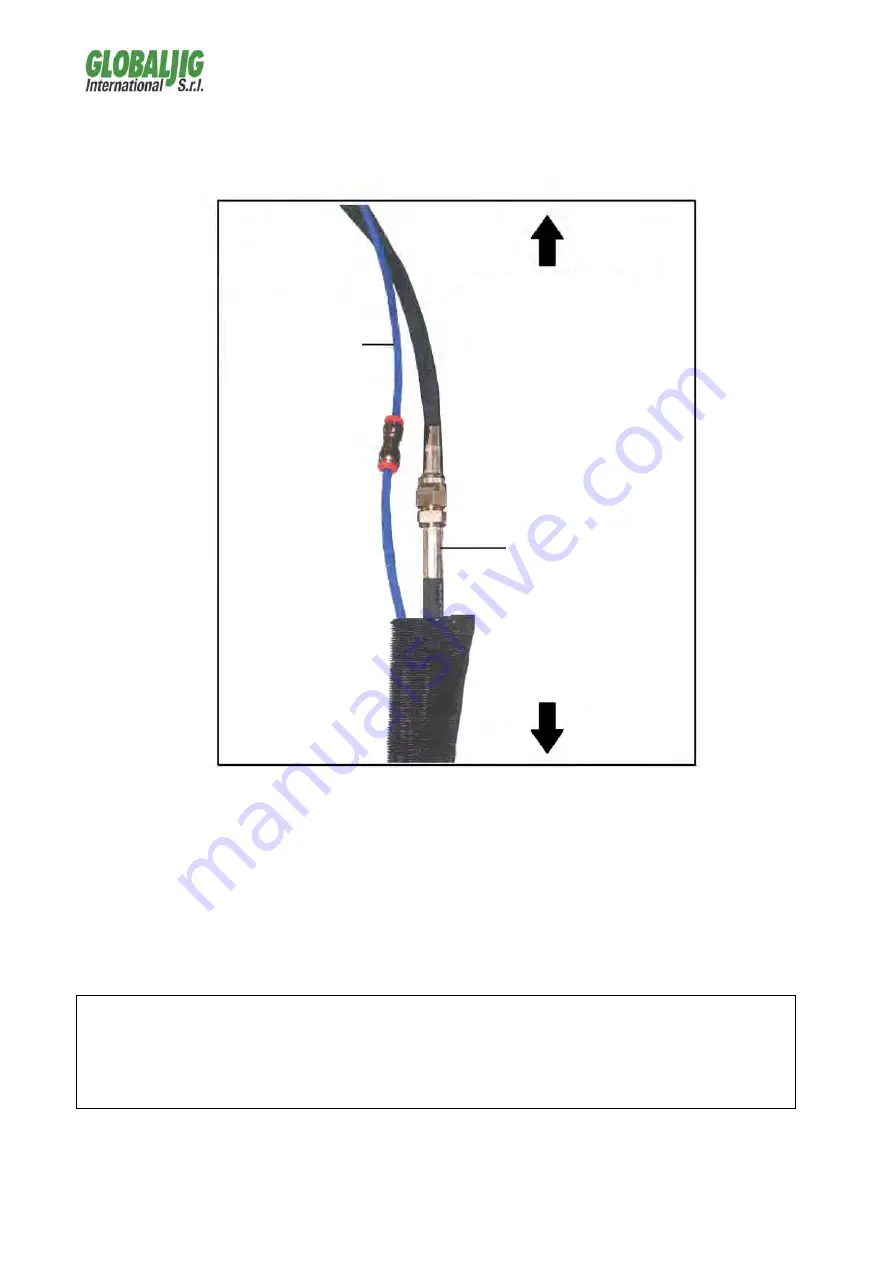
The connection between the control unit and the base of the
hydraulic power lift is made up of a sheathing which contains:
1 flexible oil-pressure tube (lift movements).
1 compressed air tube for controlling the opening of the arms;
ATTENTION
In order to avoid functional damage, REPLACE the air-tight
"transport" cap with the "working" cap (aerated) after having
positioned the control unit and before using the lift. The working cap
is found within a nylon bag inside the mobile control unit
COMPRESSED-
AIR SUPPLY
SAFETY
RELEASE
OIL PRESSURE
SUPPLY
LIFT BASE
CONTROL
UNIT
Содержание Quick Pull
Страница 1: ......
Страница 2: ......
Страница 6: ...6 2 2 Quick Pull Hydraulic Power Lift encumbrance dimensions ...
Страница 16: ...16 7 8 9 RIF CODE DESCRIPTION 7 GK3 CONTACTOR 8 GK4 TRANSFORMER 9 GK5 CIRCUIT ...
Страница 25: ...25 17 ANNEXES ...
Страница 26: ...26 ...
Страница 27: ...27 ...
Страница 28: ...28 ...
Страница 29: ...29 ...
Страница 30: ...30 ...
Страница 31: ...31 ELECTRICAL SYSTEM SCHEME ...
Страница 32: ...32 ELECTRONIC BOARD ...
Страница 33: ...33 HYDRAULICS SYSTEM SCHEME ...
Страница 36: ......
Страница 37: ......


