background image

Global Water


800-876-1172 

• 

globalw.com


- 32 - 


XVIII. 

Maintenance:


a.   Except for battery and desiccant, there are no user-serviceable parts 

inside the WL16 Data Logger. 


b.   Global Water recommends checking the batteries every 6 months. 
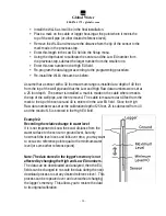
c.   Clean the sensor screen using clean water and a toothbrush to 

remove any algae, mud or sludge. 


XIX.  Troubleshooting:


Issue:  Logger is reading incorrectly. 

a.   Verify the battery supply has enough voltage.  To operate properly, the 

logger and sensor must have a minimum of 8 volts.  If the battery 

voltage monitor is reading less than 15 volts or seems incorrect, check 

the batteries with a voltmeter or replace them.  Battery voltages of less 

than 15 volts indicate that the batteries need replacing. 

b.   Check the logger and sensor calibration numbers in the Setup Menu. 

Recalibrate the logger if necessary.  As a precaution, save the setup 

file first as described in section XI.  Clean the sensor screen. 


Issue: Cannot communicate with the logger. 

a.   Verify that good batteries are installed. 

b.   Check the communication cable. 

c.   If the connection is to the WL16S using the serial cable provided by 

Global Water, verify that the correct COM port is selected in the 

connection menu of the Global Logger software. 

d.   If the connection is to the WL16U through the USB port, use the Device 

Manager to confirm that the driver is loaded and the correct virtual 

COM port is selected in the connection menu of the Global Logger 

software.  Check the Device Manager in your operating system and 

confirm that the USB COM port is not being used by another device. 

e.   Try reducing the baud rate in the connection screen of the Global 

Logger software. 

Содержание WL16S

Страница 1: ...Logger Covers WL16S and WL16U Data Loggers Global Water Instrumentation Inc 151 Graham Road P O Box 9010 College Station TX 78742 9010 T 800 876 1172 Int l 979 690 5560 F 979 690 0440 globalw globalw...

Страница 2: ...al staff will be happy to help Table of Contents I Checklist 3 II Inspection 3 III Warranty 3 IV WL16 Specifications 4 V System Requirements 6 VI Software Installation 6 VII Direct Connection 9 VIII M...

Страница 3: ...its products are free from defects in material and workmanship under normal use and service for a period of one year from date of shipment from factory Global Water s obligations under this warranty a...

Страница 4: ...re option Sensor Warm up Time Programmable 0 60 Seconds Sample Modes Fixed Interval Programmable from 1 Sec to 1 Year High Speed 10 Samples per second Logarithmic Sample Rate Approximation Exception L...

Страница 5: ...FS Supply Voltage 10 36VDC Current Draw Sum of sensor outputs Warm Up Time 10mS Min 3 sec recommended Operating Temperature 0 Not Frozen to 185 F Compensated Range 32 to 70 F submerged automatic baro...

Страница 6: ...action is needed You can start using the logger by opening the Global Logger application program Skip the next section USB Driver Installation WL16U Only With the installation CD in the CDROM drive an...

Страница 7: ...software Click No not at this time when asked if Windows Update can search for software Click Next 2 Do not let Windows automatically install the software Click Install from a specific location Click...

Страница 8: ...harm will come to your computer 5 The first half of the installation is complete The Hardware Wizard must make two passes Click Finish 6 Two drivers might be required so the Hardware Wizard may repeat...

Страница 9: ...However this communication software also supports loggers which may be programmed in a Fixed Baud Rate Mode This is useful in telemetry applications particularly when using Global Water data loggers w...

Страница 10: ...Rate menu Generally the fastest rate of 115 200 is used although long cables or other factors may require a slower setting Click Connect to make the connection If a connection is not made an error me...

Страница 11: ...g modem communication The Global Logger software will operate significantly slower than during a direct connection The Global Logger software will remember the last 4 numbers dialed and has a provisio...

Страница 12: ...ting the normal Global Logger screen will appear and operate exactly as if a direct connection was made All options and features work the same but at a reduced communication speed When connecting the...

Страница 13: ...to increase battery life Interface cables may remain connected To disconnect click on the Disconnect button This label on this button will change to Connect and clicking on it will return you to the...

Страница 14: ...urrent connection status Logger Name The logger name is a user defined name associated with a particular logger to identify one from another It is programmed in the Setup menu as described later and i...

Страница 15: ...er software to take and display a single reading as well as update the rest of the fields on the screen This data reading is not stored in the historical record and does not affect the normal recordin...

Страница 16: ...ger is set to stop logging The stop alarm is a 24 hour timer which will halt logging when enabled at the next occurrence of that time after the logger has started recording If the Alarm 1 timer is set...

Страница 17: ...cussion of that subject and links to related topics underlined in blue Clicking on the link will bring up a new window with specific information on that topic In this case Sensor Warm up time in the G...

Страница 18: ...originally indicated At the top of the screen is shown the name assigned to the logger and the number of recordings that have been retrieved At the bottom of the screen are three buttons Pack Save to...

Страница 19: ...og Digital and General The first screen to appear is General Setup At the top of the setup screen is a toolbar with three options File Action and Help File The File option allows you to exit the setup...

Страница 20: ...will restore all of the analog digital and general setup information fields to default values Only the setup menus are changed the data logger must still be programmed with the new default values A wa...

Страница 21: ...Rate Leave this set to Auto Baud Rate Only change this to a fixed baud rate if planning to use this logger in a telemetry application such as using Global Water s Global Access radio modem software O...

Страница 22: ...channel 1 only and the deviation is measured in Raw Data units where the approximate raw data range is from 0 65535 corresponding to 0 20mA To find the actual number of raw data units per engineering...

Страница 23: ...mportant data XIV Analog Setup The Analog Setup screen sets the engineering units and calibration numbers for each of the analog channels the endpoints of the bar graphs in the main screen and which o...

Страница 24: ...the data column for that channel in the historical record as well as the display of data in the main screen Click on the field to enter the unit or select from a predefined list High EU The High EU fi...

Страница 25: ...select the number of decimal places to the right of the decimal point that should appear in the historical data and in the numerical data field at the bottom of the bar graph Calibrate The Calibrate b...

Страница 26: ...ily the lowest reading the sensor can output In this example the value is zero feet which is the lowest calibration point and water level Click Next Place the sensor in the condition that will cause i...

Страница 27: ...to the main screen If no settings have changed Exit will occur immediately If settings have changed but not saved yet a message will appear that asks the user if they would like to save them now If t...

Страница 28: ...876 1172 globalw com 28 XVI Modem Cable Diagram WL16S Only The following wiring diagram is used to make a cable to connect the WL16S Data Logger to an external modem A pre wired cable is available fr...

Страница 29: ...et the logger has been factory calibrated at a range of 30 feet The High and Low EU numbers can be changed to read any range without changing the accuracy as long as the difference between them remain...

Страница 30: ...talled a mark is made on the cable where it meets the top of the well pipe and then removed The cable is measured at 40 feet from the mark to the tip of the sensor and 40 is entered in the Low EU fiel...

Страница 31: ...historical data and find the water level in the record for the reference date time or special event you are interested in Enter the setup menu and note the difference between the Low and High EU numbe...

Страница 32: ...heck the logger and sensor calibration numbers in the Setup Menu Recalibrate the logger if necessary As a precaution save the setup file first as described in section XI Clean the sensor screen Issue...

Страница 33: ...ecific problems relating to the product Be prepared to describe the problem you are experiencing including specific details of the application installation and any additional pertinent information In...

Отзывы: