background image

1

Safety Summary

The following safety precautions apply to both operating and 
maintenance personnel and must be observed during all phases 
of operation, service, and repair of this instrument. Before applying 
power, follow the installation instructions and become familiar with 
the operating instructions for this instrument.

GROUND THE INSTRUMENT

To minimize shock hazard, the instrument chassis and cabinet must 
be connected to an electrical ground. This instrument is grounded 
through the ground conductor of the supplied, three-conductor ac 
power cable. The power cable must be plugged into an approved 
three-conductor electrical outlet. Do not alter the ground connection. 
Without the protective ground connection, all accessible conductive 
parts (including control knobs) can render an electric shock. The 
power jack and mating plug of the power cable meet IEC safety 
standards.

DO NOT OPERATE IN AN EXPLOSIVE ATMOSPHERE

'RQRWRSHUDWHWKHLQVWUXPHQWLQWKHSUHVHQFHRIÀDPPDEOH

gases or fumes. Operation of any electrical instrument in such an 

HQYLURQPHQWFRQVWLWXWHVDGH¿QLWHVDIHW\KD]DUG

KEEP AWAY FROM LIVE CIRCUITS

Instrument covers must not be removed by operating personnel. 
Component replacement and internal adjustments must be made by 

TXDOL¿HGPDLQWHQDQFHSHUVRQQHO'LVFRQQHFWWKHSRZHUFRUGEHIRUH

removing the instrument covers and replacing components. Under 
certain conditions, even with the power cable removed, dangerous 
voltages may exist. To avoid injuries, always disconnect power and 
discharge circuits before touching them.

DO NOT SERVICE OR ADJUST ALONE

Do not attempt any internal service or adjustment unless another 

SHUVRQFDSDEOHRIUHQGHULQJ¿UVWDLGDQGUHVXVFLWDWLRQLVSUHVHQW

DO NOT SUBSTITUTE PARTS OR MODIFY THE INSTRUMENT

Do not install substitute parts or perform any unauthorized 

www.

.com

[email protected]

1.800.561.8187

Содержание 1410

Страница 1: ...90W DC Power Supply User Manual 1410 www com information itm com 1 800 561 8187 ...

Страница 2: ... plug of the power cable meet IEC safety standards DO NOT OPERATE IN AN EXPLOSIVE ATMOSPHERE R QRW RSHUDWH WKH LQVWUXPHQW LQ WKH SUHVHQFH RI ÀDPPDEOH gases or fumes Operation of any electrical instrument in such an HQYLURQPHQW FRQVWLWXWHV D GH QLWH VDIHW KD DUG KEEP AWAY FROM LIVE CIRCUITS Instrument covers must not be removed by operating personnel Component replacement and internal adjustments m...

Страница 3: ...roduct WARNING Do not alter the ground connection Without the protective ground connection all accessible conductive parts including control knobs can render an electric shock The power jack and mating plug of the power cable meet IEC safety standards WARNING To avoid electrical shock hazard disconnect power cord before UHPRYLQJ FRYHUV 5HIHU VHUYLFLQJ WR TXDOL HG SHUVRQQHO CAUTION Before connectin...

Страница 4: ...CTION The 1410 Power Supply is a high quality serial control type DC 5HJXODWHG 3RZHU 6XSSO 7KLV PRGHO FDQ EH RSHUDWHG DW FRQVWDQW voltage or constant current mode whose output can be varied from 0 to 30 volts This compact unit has separate 3 digit LED voltage and current meters for monitoring of the output voltage and current simultaneously In terms of operability the 1410 enables high SUHFLVLRQ F...

Страница 5: ...it The limiting current values can be preset in the full range of the rated values z Multiple units of the 1410 can be connected in series to provide higher output voltage z Multiple of the 1410 can be connected in parallel Master Slave configuration to achieve higher output current 3 SPECIFICATIONS OO VSHFL FDWLRQV DSSO WR WKH XQLW DIWHU D WHPSHUDWXUH VWDELOL DWLRQ time of 15 minutes over an ambi...

Страница 6: ... SYSTEM 1DWXUDO RQYHFWLRQ POWER CONSUMPTION VA W for rated load of AC 220 V Approximate 220 INPUT VOLTAGE Voltage Frequency 120 240 VAC 50 60 Hz Switchable Operating ambient temperature 5 40 C 10 5 DIMENSIONS AND WEIGHT Dimensions W x H x D 205 x 115 x 270 mm Weight Approximate 7 4 kg FUSE RECOMMENDED Input fuse F2 AC 100V 110V 120V 3AF AC 220V 230V 240V 2AF Internal fuse F1 500 mAF 6SHFL FDWLRQV ...

Страница 7: ...n the rear panel is set to master SRVLWLRQ DQG HLWKHU WKH RXWSXW WHUPLQDO RU WKH í WHUPLQDO LV FRQQHFWHG WR WKH 1 WHUPLQDO FKDVVLV 1 YLD WKH VKRUWLQJ EDU 1 3 23 5 7 1 19 5210 17 z Be sure to use this unit within the specified ambient temperature range listed in the specification table z Because the unit is cooled by natural convection do not place objects on top to block the convection Also user m...

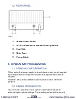
Страница 8: ...r 4 Constant Current Mode C C Indicator 5 Constant Voltage Mode C V Indicator 6 Voltage Coarse Adjust 7 Voltage Fine Adjust 8 Current Coarse Adjust 9 Current Fine Adjust 10 Output Terminal Positive 11 Output Terminal Negative 12 Ground Terminal GND www com information itm com 1 800 561 8187 ...

Страница 9: ...hen using the power supply in stand alone mode simply operate by manipulation of the panel switches and adjustment knobs as needed RZHYHU EH VXUH WKDW 0DVWHU 6ODYH 6ZLWFK LV VHW WR 0 67 5 position 1 2 6 5 211 7 21 Two or more units of the 1410 can be connected in series to achieve higher output voltage The resulting output will be sum of www com information itm com 1 800 561 8187 ...

Страница 10: ...of individual supplies and output current will be limited to within WKH YDOXH VSHFL HG IRU D VLQJOH XQLW ZKLFKHYHU LV ORZHU RU SRVLWLYH ground terminal to output positive point and for negative ground system connect the ground terminal to the negative output point 1 2 2 3 86 0 186 211 7 21 For connection as shown in Figure 4 where the intermediate point is KRRNHG XS WR JURXQG WKH FRQ JXUDWLRQ FDQ ...

Страница 11: ...wn in Figure 5 z Connect the output terminals of each of the units to the load as shown in Figure 6 For proper performance use all cables of same length and thickness z Set the voltage and current adjustment knobs of all the slave units to the maximum position z 6ZLWFK 21 WKH PDVWHU DQG VODYH XQLWV 7KH RXWSXW YROWDJH and current can then be controlled via the adjustment knobs on the master unit In...

Страница 12: ...ure 6 Figure 7 7 MAINTENANCE WARNING 7KH IROORZLQJ LQVWUXFWLRQV DUH IRU XVH E TXDOL HG SHUVRQQHO RQO To aviod electrical shock do not perform any servicing other than FRQWDLQHG LQ WKH RSHUDWLQJ LQVWUXFWLRQV XQOHVV RX DUH TXDOL HG WR GR www com information itm com 1 800 561 8187 ...

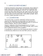
Страница 13: ...H XQLW WR OREDO 6SHFLDOWLHV IRU VHUYLFH 1 2 5 7 216 This unit has been accurately calibrated at the factory before VKLSPHQW 5H FDOLEUDWLRQ LV UHFRPPHQGHG RQO LI UHSDLUV KDYH been made in a circuit affecting calibration accuracy or if you have reason to believe the unit is out of calibration However calibrations should be attempted only if a 3 digit PXOWLPHWHU ZLWK DQ DFFXUDF RI 9 RU EHWWHU DQG D ȍ...

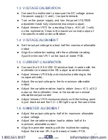
Страница 14: ... VHULHV ZLWK WKH multimeter to measure the DC output current terminals z GMXVW WULPPHU 95 IXOO DQWL FORFNZLVH UHIHUULQJ WR WKH component side z Adjust the output voltage to the its maximum allowable output z Adjust the variable resistive load to obtain Imax 0 1 0 02 amps on the multimeter Imax is the maximum nominal allowable output current z GMXVW WULPPHU 95 FORFNZLVH VORZO XQWLO WKH OLPLWLQJ SRL...

Страница 15: ...ectronics or that have been repaired by unauthorized persons will not be covered by this warranty Cal Test Electronics reserves the right to discontinue models FKDQJH VSHFL FDWLRQV SULFH RU GHVLJQ RI WKLV GHYLFH DW DQ WLPH without notice and without incurring any obligation whatsoever The purchaser agrees to assume all liabilities for any damages and or bodily injury which may result from the use ...

Страница 16: ...20160930 www com information itm com 1 800 561 8187 ...

Отзывы: