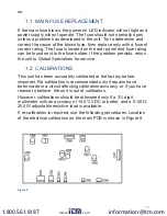
13
1.3
92/7$*(&$/,%5$7,21
z
Connect the multimeter to measure the DC voltage across
the power supply (+) and (–) output terminals.
z
7XUQRQWKHSRZHUVXSSO\DQGWXUQWKHSDQHO92/7$*(
adjustment knob fully clockwise (maximum output).
z
$GMXVWWULPPHU95IRUDUHDGLQJ9PD[YROWV
on the multimeter. Vmax is the maximum normal output of
the specific model under calibration.
1.4
92/7$*($/,*10(17
z
Set the output voltage to about half the maximum allowable
output.
z
Align the voltmeter reading with the multimeter reading.
$MXVWWKHWULPPHU95RQWKHEDFNRIPHWHU3&%
1.5
&855(17&$/,%5$7,21
z
&RQQHFWWKH±ȍ:UHVLVWLYHORDGLQVHULHVZLWKWKH
multimeter to measure the DC output current terminals.
z
$GMXVWWULPPHU95IXOO\DQWLFORFNZLVHUHIHUULQJWRWKH
component side).
z
Adjust the output voltage to the its maximum allowable
output.
z
Adjust the variable resistive load to obtain (Imax +0.1) ±0.02
amps on the multimeter. Imax is the maximum nominal
allowable output current.
z
$GMXVWWULPPHU95FORFNZLVHVORZO\XQWLOWKHOLPLWLQJSRLQW
is just reached and the C.C. LED lights up at the same time.
1.6
$00(7(5$/,*10(17
z
Adjust the output voltage to half of its maximum allowable
output voltage.
z
Adjust the variable resistive load to obtain half of its
maximum allowable current.
z
Align the ammeter reading with the multimeter reading.
$GMXVWWKHWULPPHU95RQWKHEDFNRIPHWHU3&%
www.
.com
1.800.561.8187


