Glentek Inc. 208 Standard Street, El Segundo, California 90245, U.S.A. (310) 322-3026
SMA6520 SERIES MANUAL
5
STARTUP
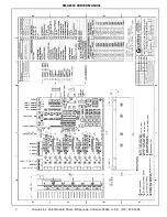
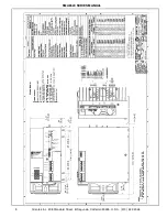
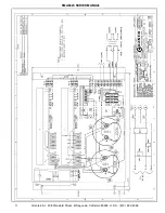
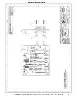
Refer to the technical specifications page and the drawings in the appendix for the information
needed to supply the correct power and to wire the model you are starting up. When the wiring is
completed and verified, the initial pot adjustments can be made. Turn on the bias supply (+/-
15Vdc), it is not necessary to connect the load or turn on the main bipolar supply yet.
2 Phase Sinusoidal Current Mode pot adjustments (Refer to 6520-11 schematic in the appendix):
Current Limit (RV1): The current limit pot sets the peak output current the amplifier can de
liver to the load. The range is +/-3A to +/-25A. Set RV1 by adjusting the pot to the desired
value by measuring the voltage at TP2, 0 volts is the minimum and 5 volts is the maximum
current.
Input Signal Gain: There are two gain pots, one for each phase, the adjustment procedure
is the same for both. The pots (RV2 & RV3) scale your input signals to the desired cur-
rents you wish to command. Apply a known input signal and adjust the pot to the desired
current using a scale factor of 4.5A/V at the test point connected to the pot wiper. Repeat
for the second phase. Avoid setting the gain such that the input signals command currents
above the current limit. This will prevent your current command signal from being clipped.
Hall Sensor/Trapezoidal Output Current Mode pot adjustments (Schematic 6520-12):
Current Limit (RV2): The current limit pot sets the peak output current the amplifier can de
liver to the load. The range is +/-0A to +/-25A. In order to set the current limit, temporarily
remove the microshunt at J4. Then adjust RV2 until the measured voltage at TP2 equals
the desired peak current (use a scale factor of 4.5A/V). Restore the J4 microshunt to its
original (current mode) position.
Balance (RV1): The balance pot can be used to deal with offsets in the amplifier and offset
in the input signal. A good initial setting is to set the wiper to the midpoint. After the load is
up and running final adjustment can be made if needed.
Input Signal Gain (RV5): The signal input gain pot scales your input signal to the current
you want to command. Apply a known input signal and adjust RV5 to the desired voltage at
TP2 using a scale factor of 4.5A/V. Avoid setting the gain such that the input signal com-
mands current above the current limit. This will prevent your current command signal from
being clipped.
These pot adjustments may be all the adjustment needed. Continue with the startup process by
connecting the load and applying the main power to the amplifier.
Содержание SMA6520 SERIES
Страница 2: ......
Страница 10: ...Glentek Inc 208 Standard Street El Segundo California 90245 U S A 310 322 3026 SMA6520 SERIES MANUAL 7...
Страница 11: ...Glentek Inc 208 Standard Street El Segundo California 90245 U S A 310 322 3026 SMA6520 SERIES MANUAL 8...
Страница 12: ...Glentek Inc 208 Standard Street El Segundo California 90245 U S A 310 322 3026 SMA6520 SERIES MANUAL 9...
Страница 13: ...Glentek Inc 208 Standard Street El Segundo California 90245 U S A 310 322 3026 SMA6520 SERIES MANUAL 10...
Страница 14: ...Glentek Inc 208 Standard Street El Segundo California 90245 U S A 310 322 3026 SMA6520 SERIES MANUAL 11...
Страница 15: ...Glentek Inc 208 Standard Street El Segundo California 90245 U S A 310 322 3026 SMA6520 SERIES MANUAL 12...
Страница 16: ...Glentek Inc 208 Standard Street El Segundo California 90245 U S A 310 322 3026 SMA6520 SERIES MANUAL 13 1...
Страница 17: ...Glentek Inc 208 Standard Street El Segundo California 90245 U S A 310 322 3026 SMA6520 SERIES MANUAL 14...
Страница 18: ...Glentek Inc 208 Standard Street El Segundo California 90245 U S A 310 322 3026 SMA6520 SERIES MANUAL 15...
Страница 19: ...Glentek Inc 208 Standard Street El Segundo California 90245 U S A 310 322 3026 SMA6520 SERIES MANUAL 16...
Страница 21: ......

