Glendinning EEC4 Скачать руководство пользователя страница 35

31

Section 2.0 — Appendix / Reference
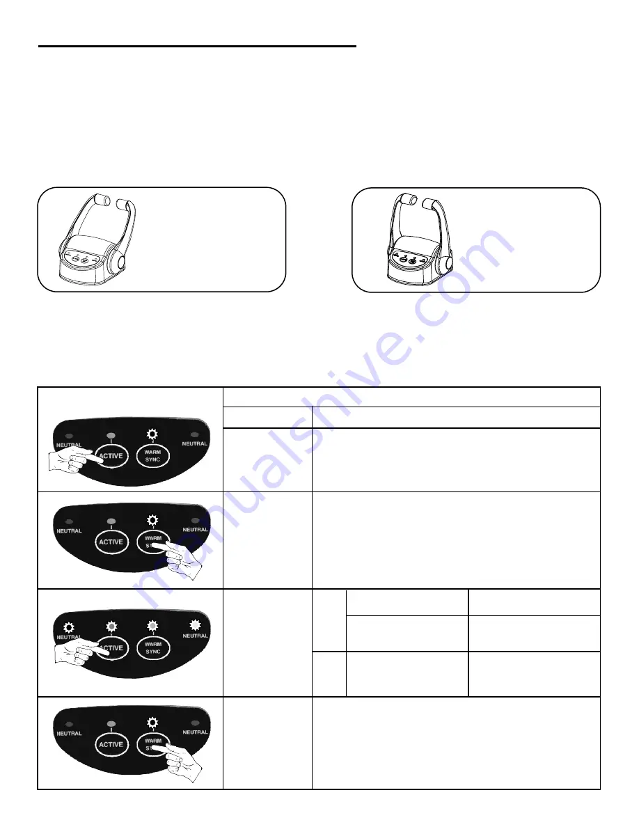
OR

Station Transfer Options

The Station Transfer Option allows you to configure the EEC system to transfer station control under-
way above idle or with handles at the Neutral position only.

Press ACTIVE 

9 times for 

Station

Transfer Option 

PORT Neutral & STBD Neutral LEDs will 

begin to flash

Press 

WARM to 

activate 

selection

NO LEDs will be illuminated

Press 

WARM to 

save option 

selection

You may continue to other configuration options 

on the following pages or you may choose to 

EXIT CONFIGURATION MODE by turning 

system OFF, moving control handles back to 

NEUTRAL, and then turn system ON again.

Press &

Release

ACTIVE 

to cycle

through Station

Transfer

Options

1

2

ACTION

LEDs ON

OPTION

None

Underway Transfer

(Default)

Port Neutral

Transfer At Neutral 

Position only

RESULT

Choose “underway transfer”  when you want 

to transfer control when handles are in appropriate 

position—not limited to Neutral gear only

(Default)

Choose “Neutral transfer” when you want to transfer 

control when handles are in Neutral only

Inactive Station “taking 

control” must be at Neutral

position in order to transfer

control from Active Station

Inactive Station “taking 

control” must have control 

handles at Neutral or in the

same gear at same or lower

speed as Active Station 

To Change Station Transfer Setting Follow These Steps:

NOTE: Active Station can be at any handle position during station transfer

Enter Configuration Mode as described in section 2.4A (pg. 29)

Содержание EEC4

Страница 1: ...EEC4 Electronic Engine Controls by Glendinning Installation Manual v3 3 Glendinning Marine Products Inc 740 Century Circle Conway SC 29526 www glendinningprods com...

Страница 2: ...MANUAL REVISIONS REVISION PAGE DESCRIPTION DATE of CHANGE 3 3 N A Initial startup of document JULY 2006...

Страница 3: ...m Test Checkout 11 2 0 Appendix References 15 2 1 Wiring Diagrams 17 Wiring Diagram Cummins QSB QSC 17 Harness Cummins QSB QSC 18 CP Pinout Description 19 2 2 Dimensional Drawings Cutout Templates 20...

Страница 4: ...he manual the NOTES symbol will appear to support what has been mentioned in the text A note can be used where further explanation is needed or where something needs highlighting BE CAREFUL to read al...

Страница 5: ...be considered Control Processor location Power Battery supply Station Communication Cable routing STBD Engine PORT Engine Circuit Breaker Circuit Breaker Battery 1 Battery 2 DC Power Harness Station C...

Страница 6: ...can operate on only a single power source Ensure that the power supply to the control system includes the following Battery sources should be independent not 2 batteries connected in parallel Circuit...

Страница 7: ...n Cable or Terminating Resistor connections Control Station Cable Terminating Resistor Photo 1 Control Head con nection points bottom view of control head Connect another control head station cable or...

Страница 8: ...d into the open CANbus connections that do not have a Station Communications cable connected to them Single Station Layout Single cable connects control head to control processor Terminating resistor...

Страница 9: ...e Control Processor Follow these steps to install the EEC4 Control Processor STEP 1 The Control Processor can be mounted anywhere in the engine room providing that the Processor is reasonably accessib...

Страница 10: ...d STEP 1 Mark the location for the Control Head using the template provided see pg 53 Cut the 3 diameter hole STEP 2 Place the Control Head assembly into the cutout STEP 3 Install Control Head clamps...

Страница 11: ...le nut handtight is sufficient 1 5 Throttle and Transmission Harness Installation A single cable harness connects the Control Processor to each engine To install this harness 1 At the Control Processo...

Страница 12: ...e transmission Or Connect the 2 FI Gear connectors on the transmission solenoids Note that each plug is marked forward or reverse connect this to the correct solenoid on the transmission Connect the 2...

Страница 13: ...ast any sharp edges ENGINE CONNECTION Control System Enable DESCRIPTION Connect the 4 pin control system enable plug to the appropriate connection on the vessel adapter harness In order to do this you...

Страница 14: ...ive connection of either battery source a Verify that the negatives of the inde pendent battery sources are connected else where on the boat 1 7 Bonding Wire Run a bonding wire 12 AWG green jacket fro...

Страница 15: ...amp fuse circuit breaker Check that all battery connections are tight Verify that Bonding Wire is properly connected to Bonding stud see sec 1 7 pg 9 Engine Gear Harness Connections Verify that all c...

Страница 16: ...l Head is OFF b Move the STBD Control Handle out of NEUTRAL position Attempt to start the STBD engine IMPORTANT If start interlock circuit does not function engine will startup in gear Be prepared to...

Страница 17: ...s Manual and transfer control from one control station to another Repeat the process until the boat owner oper ator is comfortable with the process Automatic Synchronization After the boat is underway...

Страница 18: ...and hold the ACTIVE and WARM SYNC buttons simultaneously for about 4 seconds Restore the control head lights to normal bright ness by pressing and holding the ACTIVE and WARM SYNC buttons simultaneous...

Страница 19: ...l Processor Pinout Description 19 2 2 Dimensional Drawings Cutout Templates A Control Processor Dimensions 20 B Control Head Dimensions Top Mount 21 C Cutout template for Control Head 23 2 3 Control H...

Страница 20: ...EEC4 Installation Manual 16...

Страница 21: ...t e m t o v e s e l b o n d p e r A B Y C s p e s Terminating Resistor Batteries must have a common ground To Throttle Cntr Gear Harness E n g i n e H a r n e s s 2 0 S ta ti o n STBD Throttle PORT Th...

Страница 22: ...Station Cable 40ft long 12 2 meters Station Cable 60 ft long 18 3 meters ETS Control System Harnesses Cummins Terminating Resistor Control Process End Duetsch 12 pos Grey Throttle Gear Start Interloc...

Страница 23: ...d gear Positive 2 STBD Astern Gear Positive 3 STBD Stat Interlock 1 4 STBD Ingnition CP Enable Switch Input 5 Enable Switch Power 6 Not Used 7 Not Used 8 Not Used 9 STBD Ignition Output 10 STBD Start...

Страница 24: ...onnection Throttle Ouput Station Harness Connections 2 95 75mm 3 5 88mm 6 38 162mm 7 88 200mm 7 13 181mm 12 75 324mm 10 5 267mm Transmission Start Interlock Enable EEC4 Installation Manual 20 Control...

Страница 25: ...Section 2 0 Appendix Reference 21 5 8 146 6mm 4 25 107 9mm 5 8 146 6mm 6 85 173 9mm 1 12 28 5mm 10 31 261 8mm 2 27 57 7mm 1 4 Mounting Stud 2 125 long 2 places Control Head Dimensions Top Mount...

Страница 26: ...EEC4 Installation Manual 22...

Страница 27: ...23 Section 2 0 Appendix Reference 3 25 Cutout Template for Control Head Top Mount...

Страница 28: ...EEC4 Installation Manual 24...

Страница 29: ...the 8 steps below Move control station handles to FULL ASTERN positions No result Turn power ON to the system TAKE LED will begin to flash All 4 LEDs begin to flash Press Release the ACTIVE button one...

Страница 30: ...This action stores your handle ID in memory All 4 LEDs begin to flash after ID is stored in memory N A RECORD the Handle ID on the tag locat ed on the bottom of the Control Head ACTION RESULT To Exit...

Страница 31: ...Ds begin to flash Press Release the ACTIVE button the number of times as outlined on pages 28 32 for particular SystemConfiguration Option you wish to change Appropriate LED will be illuminated see pa...

Страница 32: ...URATION MODE by turning system OFF moving control handles back to NEUTRAL and then turn system ON again Press Release ACTIVE to cycle through Throttle Delay Options 1 2 3 4 5 ACTION LEDs ON AMOUNT OF...

Страница 33: ...es for Gear Delay Option WARM LED will begin to flash Press WARM to activate selection NO LEDs will be illuminated Press WARM to save option selection You may continue to other configuration options o...

Страница 34: ...u may choose to EXIT CONFIGURATION MODE by turning system OFF moving control handles back to NEUTRAL and then turn system ON again Press Release ACTIVE to cycle through System Startup Options 1 2 ACTI...

Страница 35: ...ss Release ACTIVE to cycle through Station Transfer Options 1 2 ACTION LEDs ON OPTION None Underway Transfer Default Port Neutral Transfer At Neutral Position only RESULT Choose underway transfer when...

Страница 36: ...s Option ACTIVE STBD Neutral LEDs will begin to flash Press WARM to save option selection You may continue to other configuration options on the preceding pages or you may choose to EXIT CONFIGURATION...

Отзывы: