


5
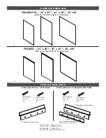
ELECTRICAL WIRING AND OUTLET LOCATION
DETERMINE THE LOCATION OF THE “Z” BRACKET
12”
12”
20.5”
17.5”
20.5”
18”
20.5”
17.5”
12”
12”
Back view of the units showing
vertical center line. Always try to
locate the outlet in the center of the
unit placed above the marked base
line of the unit as shown.
GC CHE - 3636
GC CHE - 2430
GC CHE - 2436
GC CHE - 2430
GC CHE - 2436
“Z” Bar set above base line
“Z” Bar set above base line
“Z” Bar set above base line
STEP 1 —
Measure for the Mirror
location to determine the location of
the new outlet. Mark left and right.
The bottom of the mirror should be
at least 6 inches above the surface
of any vanity sink.
TABLE 1:
BASE LINE OF
THE “Z” BRACKET
FRAMELESS: above unit
base
30” high — 26.75”
36: high — 32.75”
Landscape format:
24” high — 20.75”
FRAMED: above unit base
30” high — 26.875”
36: high — 32.875”
Landscape format:
24” high — 20.875”
Reminder: the Z bracket for
the
Framed models
must use
the shim supplied to provide
the proper clearance for the
Hanger to slide into the “Z”
bracket.
STEP 2 —
Run the new electric service from the dimmer switch to
the location for the outlet (as shown on page 4).The new outlet must
be planned to the proper location behind the mirror so that the 90º
plug from the unit installs easily without any tension on the cord. The
extra cord should lay flat within the recess in the back of the unit.