background image

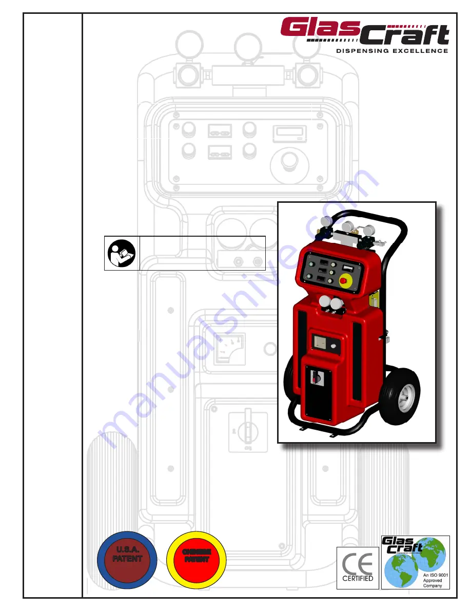
USER MANUAL

GUARDIAN

A6-6000 

Dispensing System

TH

IS

 E

Q

U

IP

ME

NT IS PRO

TE

C

T

E

D

 B

Y

CHINESE   

PATENT

ZL 200630130159.1

TH

IS

 E

Q

U

IP

ME

NT IS PRO

TE

C

T

E

D

 B

Y

U.S.A.   

PATENT

D546,840

Important Safety Instructions

Read  all  warnings  and  instructions  in 

this manual. Save these instructions.

For use with non-flammable foam and polyurea. 


Not for use in explosive atmospheres.

Содержание GUARDIAN A6-6000

Страница 1: ...Y CHINESE PATENT ZL 200630130159 1 T H I S E Q U I P M ENT IS PR O T E C T E D B Y U S A PATENT D546 840 Important Safety Instructions Read all warnings and instructions in this manual Save these ins...

Страница 2: ...ut down Instructions 19 Daily Start Up Instructions N A Section 3 General Information Assembly Drawings 23 Sub Assembly Drawings 30 Maintenance 36 Troubleshooting 37 Options 39 Section 4 Warranty and...

Страница 3: ...in approved containers and dispose of it according to applicable guide lines Always wear impervious gloves when spraying or cleaning equipment PERSONAL PROTECTIVE EQUIPMENT You must wear appropriate p...

Страница 4: ...drugs or alcohol Do not exceed the maximum working pressure or temperature rating of the lowest rated system component See Technical Data in all equipment manuals Use fluids and solvents that are com...

Страница 5: ...ecome suspended in the fluid Eventually a film will form on the surface and the ISO will begin to gel increas ing in viscosity If used this partially cured ISO will reduce performance and the life of...

Страница 6: ...w foam blowing agents will froth at temperatures above 90 F 33 C when not under pressure especially if agitat ed To reduce frothing minimize preheating in a circulation system Changing Materials When...

Страница 7: ...should be directed by a GlasCraft distributor or made from the GlasCraft Assembly instructions provided This manual provides information for the assembly opera tion maintenance and service of this Gla...

Страница 8: ...t Number Description 23675 A6 6000 UNIT 23950 02 PROBLER P2 GUN 249588 HIGH PRESSURE HOSE ASSEMBLY 256626 WHIP HOSE ASSEMBLY 23473 00 HEATER REPAIR KIT GC 1398 USER MANUAL 59934 04 DIOCTYL PHTHALATE 1...

Страница 9: ...r size needed d You will need to run an air line to the area where the machine will be placed consult the data sheet the specific unit being installed to determine much clean dry air will be needed to...

Страница 10: ...ial inlets on the bottom of the pumps and the air inlets on the air motor portion of the pumps 6 Install a y filter to the oulet of both pumps Besure to use teflon tape on the threads 7 Install a male...

Страница 11: ...se thus enabling easy removal when needed 9 Make sure that the red caps have been removed from the bottom of the pumps and then slide the transfer pumps into the collars Tighten the wing nuts on the c...

Страница 12: ...ine It is highly recommended that you label the POLY hose with BLUE tape and the ISO hose with RED tape to ensure that you don t put the wrong transfer pump in the opposite material drum 12 Connect th...

Страница 13: ...air lines p n 17798 10 that came in the transfer kit Besure to use teflon tape on the threads b Attach the quick disconnect fittings to the male receivers on the transfer pumps 14 Attach the other en...

Страница 14: ...the hose to the front of the machine Tighten the hose securely being careful not to twist the hose in an un natural bend Refer to the last page in this installation guide for instructions on how to se...

Страница 15: ...ng the first hose to the proportioner wire painting does not make a difference 24 Insert one wire from the heated hose into the connector Ensure that the ferrule is mating with the connector insert an...

Страница 16: ...ion fittings and tighten finger tight c Hold crimp fitting hex 3 4 in and union fitting together allowing the hose to hold its natural line Using 3 4 in wrenchs to tighten swivel fitting to union not...

Страница 17: ...ays live Disconnect or turn off Main Power source before opening console to make any repairs or before making any electrical repair of any type to the system If you do not understand the electrical ho...

Страница 18: ...he path of the material spray Do not point the gun at or near other personnel Do not look into the Mixing Chamber orifice at any time Because of the hazardous materials used in this equipment it is re...

Страница 19: ...sides are approximately the same pressure 5 Dispose of waste material properly and in accor dance with chemical suppliers instructions and local state and federal regulations Before re assembling Sid...

Страница 20: ...hen heated it is imperative that on cold start up of the system that the heaters be turned on and allowed to reach operating temperatures before the Main Pump Air Regulator is adjusted to the desired...

Страница 21: ...ct switch to the retract position and trigger the gun until pumps are in the down position 4 Perform gun maintenance See gun manual 5 Reduce main air regulator pressure to zero 6 Visually inspect the...

Страница 22: ...2 Use a suitable solvent to flush the fluid circuits To determine the compatibility of solvents with material being used Always check with material supplier 3 Increase transfer pump pressure until fl...

Страница 23: ...procedure from the gun manual 12 The length of time a system is shut down and the climate conditions it s stored in will determine how often the system should be purged and refilled Usually every 2 4...

Страница 24: ...erial to the Pumps 2 Turn OFF Main Air Regulator on Air Motor Gun 1 Open both Side Block Material Valves 2 Turn ON Air Switch 3 Point Gun into a clean suitable container and trigger Gun until material...

Страница 25: ...23 REVISION E Section 3 General Information Assembly Drawings 23675 XX Unit Assembly...

Страница 26: ...24 REVISION E Section 3 General Information Assembly Drawings 23675 XX Unit Assembly...

Страница 27: ...8 00 ON OFF POWER SWITCH 22502 00 CIRCULAR PANEL JACK 22509 00 CONTROL CABLE 23445 00 HEATER ASSEMBLY 23446 00 HEATER ASSEMBLY 23447 00 BOTTOM PLATE 23450 XX GUARDIAN HYBRID ASSEMBLY 23453 00 HEATER C...

Страница 28: ...26 REVISION E Section 3 General Information Assembly Drawings 23675 XX Generic System Schematic...

Страница 29: ...23675 XX System Schematic 220V Single Phase 27 Section 3 General Information Assembly Drawings REVISION E...

Страница 30: ...23675 XX System Schematic 220V Three Phase 28 Section 3 General Information Assembly Drawings REVISION E...

Страница 31: ...23675 XX System Schematic 380V Three Phase 29 REVISION E Section 3 General Information Assembly Drawings...

Страница 32: ...Section 3 General Information Sub Assembly Drawings 30 REVISION D 23450 XX Hybrid Assembly...

Страница 33: ...UT 2 23467 00 WHEEL 2 23474 00 AIR MANIFOLD 1 23476 00 FLUID MANIFOLD 1 23482 00 MANIFOLD DECAL 1 5307 01 CONDUIT NUT 4 5307 03 CONDUIT NUT 1 5363 01 COTTER PIN 2 7315 09 RUBBER GROMMET 2 7315 11 RUBB...

Страница 34: ...0 TERMINAL 6 22507 00 END COVER 3 22753 01 OVERPRESSURE DECAL 3 23456 01 CONTROL PANEL 1 Part Number Description Qty 23486 02 FEMALE PLUG 2 23486 03 FEMALE PLUG 1 23487 02 MALE PLUG 2 23487 03 MALE MA...

Страница 35: ...trical Assembly Section 3 General Information Sub Assembly Drawings 23479 03 Part Number Description Qty 21164 02 2 AMP FUSE 2 21823 00 DIN RAIL 2 4 21888 06 CIRCUIT BREAKER 3 21889 00 FUSEHOLDER 2 22...

Страница 36: ...PLUG 1 13076 18 O RING 4 20653 00 FITTING 1 21068 06C SCREW 4 21074 00 THERMOCOUPLE 1 22019 00 FIRE ROD 2 22108 00 OVERTEMP SWITCH 2 22633 00 COMPRESSION SPRING 2 23442 00 HEATER FRONT CAP 1 23443 00...

Страница 37: ...for leaks 2 Check desiccant dryer beads to insure they are still purple and have not changed to pink 3 Check and lube top of the fluid section Wipe off residual material and add a tablespoon of DOP D...

Страница 38: ...e system incorporates monitors for high pressure monitoring These monitoring devices will prevent the system from continued operation if high pressure situations develop There are pressure sensors loc...

Страница 39: ...able to locate and cure problems easily Remember however that a successful operator must know WHAT GOOD MATERIAL LOOKS LIKE HOW THE EQUIPMENT NORMALLY OPERATES WHAT PATH THE MATERIALS FOLLOW THROUGH T...

Страница 40: ...osed to the atmosphere it should be run long enough to displace the material that was in the unit when it was opened up NEVER inspect filter assemblies at time of shut down 4 In troubleshooting a rest...

Страница 41: ...39 REVISION A The transfer kit attaches the same way for both ISO POLY side Use teflon tape on NPT threads Section 3 General Information Options 17666 04 Diaphragm Transfer Pump Kit...

Страница 42: ...REVISION A 17666 05 Transfer Kit 40 Section 3 General Information Options The transfer kit attaches the same way for both ISO POLY side Use teflon tape on NPT threads...

Страница 43: ...Section 4 Safety Information Notes 41...

Страница 44: ...l Requirements 50 A 208 240 VAC 50 60 hz Single Phase 20 A 208 240 VAC 50 60 hz Three Phase 20 A 380 VAC 50 hz Three Phase Compressed Air Requirements Base Unit 1 0 GAL PER MINUTE 17 CFM 100 PSI 1 5 G...

Страница 45: ...re replaced by any parts or components not manufactured or supplied by GlasCraft The decision by GlasCraft shall be conclusive and binding on Purchaser GlasCraft does not warrant that any equipment or...

Страница 46: ...rrespondence to service glascraft com For Air Powered Systems Model _____________________________ Air compressor size __________________ Serial number _______________________ CFM generated ___________...

Страница 47: ...d contractor GlasCraft has a system package to meet your requirements GUARDIAN AIR POWERED A5 A6 SERIES EQUIPMENT 6000 OR 12000 WATTS OF HEAT 1600 2200 OR 3000 PRESSURE SET UPS AVAILABLE MH MH II MH I...

Страница 48: ...Quality and Performance GENUINE GLASCRAFT GRACO INC P O BOX 1441 MINNEAPOLIS MN 55440 1441 Phone 612 623 6921 Toll Free 1 800 328 0211 Fax 612 378 3505 www glascraft com GC 1398 REVISION E...

Отзывы: