GKB VFDS Скачать руководство пользователя страница 43

12 

(Class A) Wood-smoldered smoke generate method 

The combustible for this test is to be to ten Ponderosa pine sticks (non-resinous, free from knots or 

pitches) placed in a spoke pattern on the hotplate so that sticks are 36 degrees (0.63 rad) apart. The 

end of each stick is to be flush with the edge of the hotplate. Each stick is to be 3 by 1 by 3/4 inches 

(76.2 by 25.4 by 19.1 mm) with the 3/4 by 3 inch (19.1 by 76.2 mm) face in contact with the hotplate. 

All surfaces of each stick are to be relatively smooth and free from burrs or holes. The grain of the 

wood is to be parallel to the stick length. Each stick is to be conditioned for not less than 48 hours at 

52°C  (125°F)  in  an  air-circulating  oven.  The  stick  weight  is  to  be  16  ±2  grams  (0.56  ±0.07  oz) 

following the oven conditioning. 

Exception: The above stick dimensions and the number and placement of sticks are variable as long 

as the correct smoke buildup rates are achieved. 

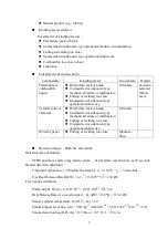
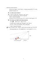
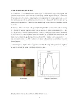
The heat source is to be a 240 volt, 1550 watt hotplate

having a steel plate 8-1/2 inches (216 mm) in 

diameter  and  1/4  inch  (6.4  mm)  thick,  the  top  most  portion  of  which  is  to  be  8  inches  (200  mm) 

above  the  floor.  The  temperature  of  the  hotplate  is  to  be  monitored  by  an  iron  constant  an  No.  30 

AWG (0.05 mm

2

) (Type J) thermocouple attached to the edge of the steel plate by placing its junction 

in a hole 0.015 inch (0.38 mm) in diameter and 1/4 inch (6.4 mm) deep and peening over the opening 

to  secure  it.  The  thermocouple  is  to  be  connected  to  a  proportioning  temperature  controller  that  is 

able  to  be  precisely  set  for  the  specified  hotplate  temperature.  The  controller  sensitivity  is  to  be 

adjusted so that all conditions for this test are met. Once set for a specific temperature, the hotplate is 

to be maintained at that temperature, (as monitored by a temperature measuring meter). Prior to the 

start  of  the  test,  the  hotplate  temperature  is  to  be  23  ±2°C  (73  ±4°F).  The  initial  proportioning 

controller  temperature  setting  is  to  be  205°C  (401°F).  The  hotplate  and  controller  are  then  to  be 

energized and the test time started (T = 0). The proportioning controller setting is to be increased to 

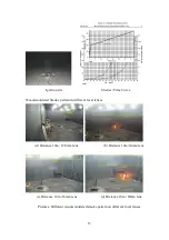
obtain  the  temperature  sequence  specified  in  Table  40.1  and  Figure  40.1  (the  hotplate  temperature 

normally lags the controller setting by 2 minutes during the incremental increases). 

Содержание VFDS

Страница 1: ...VFDS Video Fire Detection System System Design Manual V3 1 English GKB SECURITY CORPORTATION...

Страница 2: ...arget setup 4 2 2 Detection environment investigation 5 2 3 Hazards analysis and scenario Design Considerations setup 7 2 4 Detection time definition 10 2 5 Hazard Detection Definition 11 2 6 Fire smo...

Страница 3: ...s the VFDS provides many extra advantages 1 Early stage alarm VFDS may prevents serious damage and millions of lost by recognizing fire and smoke at an early stage VFDS detects both flame and smoke co...

Страница 4: ...figuration Alarm Output VFDS window alarm sound alarm video recording digital signal output and dry contact point output alarm box and mobile text message Processing log and alarm videos playback Vide...

Страница 5: ...ed protecting area design flow chat as follows Set protection areas Investigate field space Illumination conditions Fire hazard analysis and set fire scenario Decide VFDS reaction time Define and esti...

Страница 6: ...nvironment such as high ceiling hall or wide open space Define the protection area where usually is high risk Please refer to Pic 2 1 1 Generally VFDS system designers position the system as the early...

Страница 7: ...level of object and unit measure is Lux Averagely each square meter with one lux light on is defined as 1Lux Field illumination control There are specific cameras for VFDS to achieve precious detectio...

Страница 8: ...ht spread Field background color VFDS system bases on the image processing to detect fire and smoke When the background color is similar color to the possible flame or smoke hazard it may effect VFDS...

Страница 9: ...d their alloy Ignition Sources factor analysis Investigate possible ignition sources in the environment Some possible ignition sources are as follows Energized electrical sources include short circuit...

Страница 10: ...ft meters high 6 12 moisture Medium Fast Wood pallets stacked 10 ft meters high 6 12 moisture Fast Wood pallets stacked 16 ft high Meters 6 12 moisture Fast Mail bags filled stored 5 ft high meters F...

Страница 11: ...9 Gasoline Ultra fast Kerosene Ultra fast Diesel Oil Ultra fast...

Страница 12: ...prevent the fire formation is the value of VFDS Fire alarm should be triggered during the incubation period In NFPA 92B the recommend heat release rate is 1 055kW Use the Ultra fast Fast Medium and S...

Страница 13: ...th rate of fire ignition kW s2 Refer to Table 2 5 1 t g Effective ignition time s the alarm trigger time Table 2 5 1 T Squared Fires Growth Rate Coefficient Item description Growth rate kW s2 Slow 0 0...

Страница 14: ...lculation The smoke volume and height has a lot of to do with VFDS smoke detection limit Hence the system designer needs to predict or define the minimum size height of possible smoke arose or need to...

Страница 15: ...13 Pic 2 6 2 Smoke height calculation Height m Width m...

Страница 16: ...w 2 8mm 4 mm 6 mm 8 mm 12 mm Camera viewable angel and coverage calculation Different focal lengths in the camera lenses provide different viewable angle and coverage Usually it is present in the form...

Страница 17: ...ession angle 2 degree 2 tan 1 Dv 2f Camera image vertical viewable angel Dv is CCD vertical length f is focal length value Pic 2 7 3 Parameters of camera installation Image detection distance calculat...

Страница 18: ...for each camera will be the smaller value of either Df or Ds According to the shortest and farthest detection distance the detection area can be drawn out as sector shape Please refer to the yellow r...

Страница 19: ...the whole region to be set as the required protection region is highly recommended Pic 2 7 4 Camera focal length and viewable angel relation a Wide viewable angle but short detection distance inadequa...

Страница 20: ...e the camera cover all the range overlapping cameras view angle is a safer way for installation Fig 2 7 5 Recommended cameras installation in rectangular space Fig 2 7 6 Recommended cameras installati...

Страница 21: ...Horizontal angles a Correct Angle 45 b Prohibited Angle 45 c Correct Angle 45 d Prohibited Angle 45 Pic 2 7 7 Interior space Height 4 meters camera depression angel Avoid the camera looking directly t...

Страница 22: ...low as a factor for correct detection on the fire and smoke Lens clarity factor Lens is the eye to the camera as the eyes to human The blemish on the lens blocks the image which affects the detection...

Страница 23: ...21 c Correct High risk area d Correct Vacant area c Correct High risk area d Correct Vacant area Pic 2 7 9 Camera installation recommendation...

Страница 24: ...ead zone settings Above the dead zone demarcation it is no moving object area and under the demarcation it is the area with moving objects Appropriate setting of demarcation will shorten detection tim...

Страница 25: ...affect the accuracy of detection Also refer to Pic 2 8 4 a In Pic 2 8 3 b the camera is set to 3 4 level of ALC the image is with appropriate brightness and more stable It causes little variation by...

Страница 26: ...rent ALC Levels with Black Object VFDS Camera Parameter Setup In this paragraph VFDS system designer has to set up camera parameters in the server configuration pages Enter VFDS main screen click Setu...

Страница 27: ...917DVFP C If using a none GKB CCTV camera the suggested settings are as below Camera Option Camera with IR Camera_with_IR Camera w o IR Camera_without_IR Note It would affect the detection accuracy if...

Страница 28: ...c Detection Environment Setup 1 Please define the environment of the target area an indoor place or an outdoor one by selecting the background option 2 Please select the target area luminance conditi...

Страница 29: ...area in the screen Intend detecting flame of a small area in the screen Default Not crowded normal indoor space No limitation No limitation Smoke High Sensitivity Area of high risk in fire event and n...

Страница 30: ...he area close to the ceiling due to the thermal buoyancy as shown in the photo The red area stands for an area where the smoke is accumulated Others refer to areas which are used as the normal detecti...

Страница 31: ...ection or not The main purpose of this option is to meet client s requirements and to lower the false alarms Users can make screen masks freely and decide the detection option for each mask Relevant i...

Страница 32: ...e 100 Lux meet VFDS requirements Field illumination condition Interior with always opened illumination Choose camera model CHQ 8986WTM 8 accordingly Field background color None monochrome simple black...

Страница 33: ...r chemical Part failure leak or break Unclassified or unknown type mechanical failure or malfunction Cutting or welding too close Unclassified or unknown type operational deficiency Ultra fast Wood or...

Страница 34: ...cal length Calculate horizontal viewable angle is 43 6 vertical viewable angle is 33 4 Detection nearest limit dead angle estimation CCD 3 1 Width 4 8mm Height 3 6 mm Camera vertical viewable angel 2...

Страница 35: ...e to detect smoke CCD 3 1 with width 4 8mm height 3 6 mm Real smoke reflection height Hp Hs cos 1 13 4 m cos 30 11 6 m VFDS smallest smoke detection limit height ratio 30 240 0 125 CCD hf VFDS height...

Страница 36: ...cording to the farthest detection distance and horizontal viewable angel Camera width coverage W 2 30 2 tan 43 6 2 24 2 m The final design for the field is to set two cameras across to cover most terr...

Страница 37: ...a rod 1 inch in diameter until the paper level is 4 inches below the top edge of the receptacle A hole 1 inch in diameter is to be formed through the center from top to bottom of the paper The tempor...

Страница 38: ...per oriented fire in different focal lenses a Distance 10m f2 8mm lens b Distance 10m f4mm lens c Distance 10m f6mm lens d Distance 10m f8mm lens Pictures Different paper generated smoke pattern on di...

Страница 39: ...denatured alcohol consisting of 190 proof 95 percent ethanol to which 5 percent methanol is added as a denaturant The alcohol is to be placed in a 1 1 2 inch 38 mm diameter 1 inch 25 4 mm deep metal c...

Страница 40: ...9 b Distance 10m f2 8mm lens b Distance 10m f4mm lens c Distance 10m f6mm lens d Distance 10m f8mm lens Pictures Different wood generated smoke pattern on different focal lenses...

Страница 41: ...m stainless steel 6 1 4 inches 158 mm in diameter and 1 1 4 inch 32 mm deep rounded bottom formed by 1 2 inch 12 7 mm radius Located 3 feet 0 9 m above the test room floor and centered with a ring sup...

Страница 42: ...id combustibles fire in different focal lenses c Distance 10m f2 8mm lens b Distance 10m f4mm lens c Distance 10m f6mm lens d Distance 10m f8mm lens Pictures Different liquid generated smoke pattern o...

Страница 43: ...1 4 inch 6 4 mm thick the top most portion of which is to be 8 inches 200 mm above the floor The temperature of the hotplate is to be monitored by an iron constant an No 30 AWG 0 05 mm2 Type J thermoc...

Страница 44: ...ve Wood smoldered Smoke pattern in different focal lenses d Distance 10m f2 8mm lens b Distance 10m f4mm lens c Distance 10m f6mm lens d Distance 10m f8mm lens Pictures Different wood smoldered smoke...

Отзывы: