background image


User Manual


Intrinsically Safe Ultrasonic Anemometer 

Doc No: 1360-PS-0001 

Issue 10


(Applies to Anemometers with Serial Numbers 3000 onwards)


Parts 1360-PK-022 


and 1360-PK-060 


Gill Instruments Limited 

Saltmarsh Park, 67 Gosport Street, Lymington, 

Hampshire, SO41 9EG, UK 

Tel: +44 1590 613500, Fax: +44 1590 613555  

             Email: 

[email protected]

  Website: 

www.gillinstruments.com

Содержание 1086-G-045

Страница 1: ...Applies to Anemometers with Serial Numbers 3000 onwards Parts 1360 PK 022 and 1360 PK 060 Gill Instruments Limited Saltmarsh Park 67 Gosport Street Lymington Hampshire SO41 9EG UK Tel 44 1590 613500...

Страница 2: ...Gill Instruments Ltd Intrinsically Safe WindObserver Anemometer Page 2 Issue 10 Doc No 1360 PS 0001 May 2015 WARNING ENSURE CORRECT SUPPLY VOLTAGE IS USED SELECTED ON POWER SUPPLY BEFORE INSTALLATION...

Страница 3: ...mometer Installation Details 21 5 2 6 Alignment 22 Drawing 1360 G 026 Issue 1 Type IIc I S Anemometer Dimensions 22 5 2 7 Sealing 23 5 2 8 Corrosion 23 5 2 9 Earthing 23 5 2 10 General 23 6 SYSTEM OPE...

Страница 4: ...rver Anemometer Page 4 Issue 10 Doc No 1360 PS 0001 May 2015 APPENDIX 1 62 SUMMARY OF ABBREVIATIONS USED IN THIS MANUAL 62 APPENDIX 2 64 PRODUCT APPROVALS 64 SIRA ATEX CERTIFICATION 64 SIRA IECEx CERT...

Страница 5: ...WindObserver is a very robust unit with no moving parts outputting wind speed and direction The units of wind speed output rate and formats are all user selectable The Intrinsically Safe WindObserver...

Страница 6: ...Head Cover 2 halves 1360 PK 055 Intrinsically Safe Power Supply Unit and Communications 1954 00 002 Interface Low Voltage Power Supply 1360 10 008 3 Metre Anemometer Test Cable 3 3 Spares 1360 PK 052...

Страница 7: ...emometer Status Supplied as part of standard message Power Requirement Anemometer only 6V 12VDC 30mA peak from Gill ATEX IECEX Certified Power and Communications Box only all circuits protected to 0 8...

Страница 8: ...n Digital Outputs RS232 and RS422 Interface Data to from IS WindObserver Power Requirement Input Power 100Vac 120Vac 10VA for the 115V switch position 200Vac 250Vac 10VA for the 230V switch position O...

Страница 9: ...ce Data to from IS WindObserver Power Requirement Input Power 9v to 30v dc at 200mA max Fused 20mm 1 amp anti surge Galvanic isolation between input power and anemometer supply Output Power 10 5v dc a...

Страница 10: ...Gill Instruments and must be determined to be suitable for use by the customer IS cable resistance must not exceed 17 ohms in each cable wire run E g If using 24 awg wire with cable resistance of 0 0...

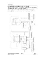
Страница 11: ...Supply The unit must be installed in accordance with the Control Drawing 1360 G 028 Note that the PCI box is mounted in the Non Hazardous area Drawing 1360 G 028 I S Issue 3 IS WindObserver System Dia...

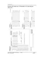
Страница 12: ...Gill Instruments Ltd Intrinsically Safe WindObserver Anemometer Page 12 Issue 10 Doc No 1360 PS 0001 May 2015 Drawing 1360 G 028 Issue 3 I S WindObserver System Diagram Sheet 2 of 2...

Страница 13: ...10 Doc No 1360 PS 0001 May 2015 5 1 2 Installation using a Low Voltage Power Supply The unit must be installed in accordance with the Drawing 1954 30 026 Note that the PCI box is mounted in the Safe...

Страница 14: ...Gill Instruments Ltd Intrinsically Safe WindObserver Anemometer Page 14 Issue 10 Doc No 1360 PS 0001 May 2015 Drawing 1954 30 026 issue 3 IS WindObserver System Diagram Sheet 2 of 2...

Страница 15: ...outside this range 4 Installation shall be carried out in accordance with the applicable code of practice by suitably trained personnel 5 There are no special checking or maintenance conditions other...

Страница 16: ...ambient temperatures in the range 30 C to 40 C and should not be used outside this range 6 Installation shall be carried out in accordance with the applicable code of practice by suitably trained per...

Страница 17: ...20 21 22 with flammable dusts fibres and flyings in groups IIIA IIIB and IIIC T135 C 5 Installation shall be carried out in accordance with the applicable code of practice by suitably trained personn...

Страница 18: ...lines of sight Ensure the product is correctly earthed in accordance with this manual Use cables recommended for the IS installation keeping the length below the maximum allowed see Pages 19 and 25 Wh...

Страница 19: ...th IS cable resistance must not exceed 17 ohms in each cable wire run E g If using 24 awg wire with cable resistance of 0 08 ohms per metre then maximum cable run is 213 Metres If using 22 awg wire wi...

Страница 20: ...Anemometer 5 22 4 RX RS422 Receive Data to the Anemometer 6 26 8 Supply ve 14 25 7 Supply ve 19 or 20 1 or 2 Cable Screen Arrange IS WindObserver Connector Parts as Follows Align the 20 way plug rotat...

Страница 21: ...g the Anemometer from its box to its install location the supplied head cover parts 1277 30 045 should be fitted around the anemometer head see below and secured in place using supplied Tyraps Upon in...

Страница 22: ...ignment The anemometer should be set to point North see drawing 1360 G 026 as shown below or to some other known reference direction This is facilitated by slots in the base for the mounting screws wh...

Страница 23: ...ntrinsically safe operation will be affected if incorrectly earthed An Earth terminal is located at the base of the IS Anemometer and to ensure correct operation and for maximum protection against lig...

Страница 24: ...AC operation is required then set the internal slide switch to the 115V setting Changing the supply voltage may be accomplished by first ensuring mains power is not applied to the Power Supply box Ope...

Страница 25: ...The anemometer outputs wind data through a single 20 way circular connector in the base Details of the pin allocations can be found on Page 20 Data is provided in Digital format Connecting to a PC or...

Страница 26: ...coupled to a WindDisplay the Intrinsically Safe WindObserver can be used as supplied however if a fault occurs the WindDisplay may lock into the last valid reading Re configuring the Intrinsically Saf...

Страница 27: ...bold and for convenience some Configuration codes as used to set the configuration are shown in blue boxes For example M3 Wind Speed format The wind speed measurements can be output in one of the foll...

Страница 28: ...ring character ASCII value 3 CC Checksum of all Characters between STX and ETX HEX byte CR LF Carriage Return and LineFeed 1 In Feet per Minute output mode the string changes to UUUU U 2 In Feet per M...

Страница 29: ...s between STX and ETX HEX byte CR LF Carriage Return and LineFeed 1 In Feet per Minute output mode the string changes to UUUU U 2 In Feet per Minute output mode the string changes to VVVV V Mode 4 ASC...

Страница 30: ...Direction in degrees R Relative wind measurement MMM MM Wind Speed U Units M m s N knots P mph K kph F fpm A Data Status flag A Acceptable V Void Checksum delimiter cc Checksum Exclusive OR of all ch...

Страница 31: ...l read like 0x81 0x81 006 04 265 00 1 STX MMM MM DDD SS U ETX CR LF Where STX Start of string character ASCII value 2 MMM MM Wind Magnitude along U axis DDD Wind Magnitude along V axis SS Status Code...

Страница 32: ...average building completed Status code 00 reported A M15 000 000 02 M 000 000 06 04 45 CSV data fault condition status code 04 A M15 000 000 03 M 04 6C CSV data with fault condition remaining A M15 M...

Страница 33: ...th continuous fault condition A M15 296 000 01 M 174 000 08 04 47 Fixed Field fault condition status code 04 A M15 296 000 02 M 999 999 99 04 4E Fixed Field with fault condition remaining A M15 999 99...

Страница 34: ...raged Digital Data Output comprises of Start of String Node Mode Averaged Direction Averaged Magnitude units Maximum Gust Direction Maximum Gust Magnitude Status End of String checksum e g status code...

Страница 35: ...period and reset at the end of short term output period The maximum Gust Magnitude is the magnitude of the maximum gust measured over the short term output period Gust is generated from a rolling 3s...

Страница 36: ...xx Long Term Number where xx is a number from 1 to 10 Once set for Mode 14 to Poll for averaged data use the command followed by the unit designator A default setting ensure capital letter used When...

Страница 37: ...put generated Enable Polled mode None Disable Polled mode None Request WindObserver Unit Identifier A Z as configured Enter Configuration mode N CONFIGURATION MODE It is suggested that in polled mode...

Страница 38: ...M 0 0 04 Low Wind Speed Condition Less than 0 05m s If wind speed is below 0 05m s then the direction parameter in ASCII modes will remain blank in CSV mode and in fixed field mode the direction param...

Страница 39: ...volatile memory EEPROM holds the user set up internal system parameters and calibration data If the internal checksum programmed in production does not match the one calculated by the system during o...

Страница 40: ...n PC s up to and including Windows 8 and can be downloaded from http www gillinstruments com main software html 9 1 Configuring using HyperTerminal Note Other terminal emulators are configured in a ve...

Страница 41: ...ault settings are Bits per second 9600 Data bits 8 Parity None Stop bits 1 Flow Control None Click on OK and data similar to the following example will scroll on screen at the output rate The WindObse...

Страница 42: ...ON MODE message stops reporting wind measurements and waits for a command as detailed below So for Example Type may take more than one attempt This will bring up the text CONFIGURATION MODE Type D1 an...

Страница 43: ...efore the poll identifier to cater for the event that the power has been switched off or power interrupted Checking the configuration We strongly recommend that as a standard procedure you use this co...

Страница 44: ...mode Type Q and press the ENTER key it will be in NMEA format Note The factory set default settings are shown in bold in the following sections 9 2 Configuration Settings Settings applicable to the IS...

Страница 45: ...heck D6 See Para 10 6 Bench Tests Fx Data and Parity Options Setting Configuration code 8 bits no parity 1 stop bit F1 8 bits even parity 1 stop bit F2 8 bits odd parity 1 stop bit F3 Gx to Gxxxx Aver...

Страница 46: ...uous Averaged M15 Nx Node Address A default Item Options Command Node Address A A to Z N A Ox ASCII Output Format Output String Padding Setting Configuration code Comma Separated Variable CSV O1 Fixed...

Страница 47: ...ding V1 Enable vertical output padding V2 Xx 45 Alignment Offset Inverted Operation Setting Configuration code Notes Align U axis with transducer axis X1 X1 Aligns U axis with North South axis Align U...

Страница 48: ...al will void the Warranty Calibration and Certification In the event of failure prior to returning the unit to your authorised Gill distributor it is recommended that All cables and connectors are che...

Страница 49: ...OM port Set the Baud rate to 19200 baud if using the Wind Terminal program it opens at 19200 baud To Place the unit into Safe Mode Turn off the IS WindObserver power supply Ensure the Terminal program...

Страница 50: ...view data 10 5 Status error codes The Status code is sent as part of each wind measurement message Code Status Condition 00 OK Sufficient samples in average period A OK NMEA data Acceptable 01 Axis 1...

Страница 51: ...l the Anemometer rock on the transducers If this occurs then it is likely the transducer arms are misaligned requiring return to Gill Instruments for re alignment 10 6 2 Connections and tests with the...

Страница 52: ...FE and 5v HAZ LED s will be illuminated Data Tests With the Sensor connected and outputting data to the PCI box Examine the Main PCB and the Red RX LED at the bottom left of the PCB will be seen to fl...

Страница 53: ...ther than these refer to Page 41 Status error codes 3 Use an office fan or similar to check that the unit is sensing wind turning the unit to simulate changing wind direction and to check that both ax...

Страница 54: ...ill Instruments Alignment Check Ensure the Protective Cover is assembled correctly on the IS WindObserver Using HyperTerminal enter Configuration Mode as described in Section 9 Type in D6 and press En...

Страница 55: ...Terminal 3 Green Green and Black Pair RS422 Data ve to Anemometer Config only Terminal 4 Black Green and Black Pair RS422 Data ve to Anemometer Config only Terminal 5 Black White and Black Pair RS422...

Страница 56: ...damage to the Anemometer might result The IS anemometer current through J5 Terminal 8 will typically be 14mA maximum 30mA When the IS Power Supply is powered up the 5v NON HAZ and 5v HAZ LED s will be...

Страница 57: ...n these refer to Page 41 Status error codes 4 Use an office fan or similar to check that the unit is sensing wind turning the unit to simulate changing wind direction and to check that both axes are f...

Страница 58: ...ver Using HyperTerminal enter Configuration Mode as described in Section 9 Type in D6 and press Enter A typical report as shown below will be displayed D6 ALIGMENT LIMITS U 2424 2524 V 2434 2434 ALIGN...

Страница 59: ...Gill Instruments Ltd Intrinsically Safe WindObserver Anemometer Page 59 Issue 10 Doc No 1360 PS 0001 May 2015 11 DRAWINGS 11 1 Mains Power Supply Drawing 1360 M 039 Issue 3 I S Terminal Arrangement...

Страница 60: ...60 Issue 10 Doc No 1360 PS 0001 May 2015 11 2 Mains Power Supply Drawing 1360 G 043 Issue 2 I S PCI Unit VIEW OF PCI WITH LID OPEN The Gland plate may be removed to allow fitting of customer supplied...

Страница 61: ...Gill Instruments Ltd Intrinsically Safe WindObserver Anemometer Page 61 Issue 10 Doc No 1360 PS 0001 May 2015 11 3 Low Voltage Power Supply Drawing 1954 30 023 issue 2 Terminal Arrangement...

Страница 62: ...Erasable Programmable Read Only Memory EMC Electro Magnetic Compatibility ETX End of string character FPM Feet Per Minute GND GrouND HEX Hexadecimal HZ Hertz IP65 Ingress Protection Classification I S...

Страница 63: ...er Anemometer Page 63 Issue 10 Doc No 1360 PS 0001 May 2015 SEC SECond RAM Static Random Access Memory STX Start of string character S W SoftWare TX Transmit UV Cartesian Co ordinate System V Volts V...

Страница 64: ...upply Unit 1360 5 Certificate Number Sira IECEx SIR 15 0013 Issue 0 for the model 1360 IS II Anemometer 6 Certificate Number Sira IECEx SIR 13 0159 Issue 1 for the IS Low Voltage Power Supply and Comm...

Страница 65: ...Gill Instruments Ltd Intrinsically Safe WindObserver Anemometer Page 65 Issue 10 Doc No 1360 PS 0001 May 2015 Certificate Number Sira 00ATEX2217 for the IS WindObserver Power Supply Unit 1360...

Страница 66: ...Gill Instruments Ltd Intrinsically Safe WindObserver Anemometer Page 66 Issue 10 Doc No 1360 PS 0001 May 2015...

Страница 67: ...Gill Instruments Ltd Intrinsically Safe WindObserver Anemometer Page 67 Issue 10 Doc No 1360 PS 0001 May 2015...

Страница 68: ...Gill Instruments Ltd Intrinsically Safe WindObserver Anemometer Page 68 Issue 10 Doc No 1360 PS 0001 May 2015...

Страница 69: ...Gill Instruments Ltd Intrinsically Safe WindObserver Anemometer Page 69 Issue 10 Doc No 1360 PS 0001 May 2015...

Страница 70: ...Gill Instruments Ltd Intrinsically Safe WindObserver Anemometer Page 70 Issue 10 Doc No 1360 PS 0001 May 2015 Certificate Number Sira 15ATEX2014 for the model 1360 IS Anemometer...

Страница 71: ...Gill Instruments Ltd Intrinsically Safe WindObserver Anemometer Page 71 Issue 10 Doc No 1360 PS 0001 May 2015...

Страница 72: ...Gill Instruments Ltd Intrinsically Safe WindObserver Anemometer Page 72 Issue 10 Doc No 1360 PS 0001 May 2015...

Страница 73: ...truments Ltd Intrinsically Safe WindObserver Anemometer Page 73 Issue 10 Doc No 1360 PS 0001 May 2015 Certificate Number Sira 23ATEX2384 for the IS Low Voltage Power Supply and Communications Unit 195...

Страница 74: ...Gill Instruments Ltd Intrinsically Safe WindObserver Anemometer Page 74 Issue 10 Doc No 1360 PS 0001 May 2015...

Страница 75: ...Gill Instruments Ltd Intrinsically Safe WindObserver Anemometer Page 75 Issue 10 Doc No 1360 PS 0001 May 2015...

Страница 76: ...Gill Instruments Ltd Intrinsically Safe WindObserver Anemometer Page 76 Issue 10 Doc No 1360 PS 0001 May 2015...

Страница 77: ...Gill Instruments Ltd Intrinsically Safe WindObserver Anemometer Page 77 Issue 10 Doc No 1360 PS 0001 May 2015 Certificate Number Sira IECEx SIR 13 0156 for the IS WindObserver Power Supply Unit 1360...

Страница 78: ...Gill Instruments Ltd Intrinsically Safe WindObserver Anemometer Page 78 Issue 10 Doc No 1360 PS 0001 May 2015...

Страница 79: ...Gill Instruments Ltd Intrinsically Safe WindObserver Anemometer Page 79 Issue 10 Doc No 1360 PS 0001 May 2015...

Страница 80: ...Gill Instruments Ltd Intrinsically Safe WindObserver Anemometer Page 80 Issue 10 Doc No 1360 PS 0001 May 2015...

Страница 81: ...Gill Instruments Ltd Intrinsically Safe WindObserver Anemometer Page 81 Issue 10 Doc No 1360 PS 0001 May 2015...

Страница 82: ...Gill Instruments Ltd Intrinsically Safe WindObserver Anemometer Page 82 Issue 10 Doc No 1360 PS 0001 May 2015 Certificate Number Sira IECEx SIR 15 0013 for the model 1360 IS Anemometer...

Страница 83: ...Gill Instruments Ltd Intrinsically Safe WindObserver Anemometer Page 83 Issue 10 Doc No 1360 PS 0001 May 2015...

Страница 84: ...Gill Instruments Ltd Intrinsically Safe WindObserver Anemometer Page 84 Issue 10 Doc No 1360 PS 0001 May 2015...

Страница 85: ...ts Ltd Intrinsically Safe WindObserver Anemometer Page 85 Issue 10 Doc No 1360 PS 0001 May 2015 Certificate Number Sira IECEx SIR 13 0159 for the IS Low Voltage Power Supply and Communications Interfa...

Страница 86: ...Gill Instruments Ltd Intrinsically Safe WindObserver Anemometer Page 86 Issue 10 Doc No 1360 PS 0001 May 2015...

Страница 87: ...Gill Instruments Ltd Intrinsically Safe WindObserver Anemometer Page 87 Issue 10 Doc No 1360 PS 0001 May 2015...

Страница 88: ...Gill Instruments Ltd Intrinsically Safe WindObserver Anemometer Page 88 Issue 10 Doc No 1360 PS 0001 May 2015...

Страница 89: ...Gill Instruments Ltd Intrinsically Safe WindObserver Anemometer Page 89 Issue 10 Doc No 1360 PS 0001 May 2015...

Страница 90: ...armonised standards and IEC Standards Model 1360 IS Anemometer EMC EN 61000 6 3 2007 EN 61000 6 1 2007 Intrinsic Safety EN60079 0 2012 EN60079 11 2012 EN60079 26 2007 IEC60079 0 2011 Edition 6 0 IEC60...

Страница 91: ...Power Supply and Communications Unit 1954 00 002 by Notified Body 0518 as Group II Category I equipment bearing the markings Anemometer II I GD Ex ia IIC T4 Ga Ex ia IIIC T135 C Da IP66 Ta 30 C to 70...

Отзывы: