


System Appearance
- 20 -
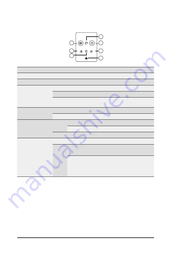
2-5 Front Panel LEDs and Buttons
1
3
2
5
7
4
6
No. Name
Color
Status
Description
1.
ID Button
Press the button to activate system identification
2.
Reset button
--
--
Press this button to reset the system.
3.
Power button
with LED
Green
On
Indicates the system is powered on.
Green
Blink
System is in ACPI S1 state (sleep mode).
N/A
Off
•
System is not powered on or in ACPI S5 state (power
off)
4 & 5.
LAN1/2 Active/
Link LED
Green
Blink
Indicates data trasmission or receiving is occuring.
N/A
Off
Indicates no data transmission or receiving is occuring.
6.
HDD Status
LED
Amber
On
Indicates locating the HDD.
Blink
Indicates accessing the HDD.
N/A
Off
Indicates HDD error.
7.
System
Status LED
N/A
Solid On System is operating normally.
Red
Solid On
Critical condition, may indicate:
System fan failure; System temperature
Blink
Non-critical condition, may indicate:
Redundant power module failure
Temperature and voltage issue
Chassis intrusion
Содержание S251-3O0
Страница 1: ...S251 3O0 Intel Xeon Scalable UP Server System 2U 26 Bay User Manual Rev 1 0...
Страница 10: ...10 This page intentionally left blank...
Страница 15: ...15 Hardware Installation 1 3 System Block Diagram...
Страница 16: ...Hardware Installation 16 This page intentionally left blank...
Страница 24: ...System Appearance 24 This page intentionally left blank...
Страница 39: ...25 System Hardware Installation HDD Backplane Board Signal Cable PSU Front Rear PSU Front Rear...
Страница 43: ...25 System Hardware Installation On Board SATA PSU Front Rear SATA1 SGPIO SATA0 Mini SAS HD PSU Front Rear...
Страница 44: ...System Hardware Installation 26 This page intentionally left blank...
Страница 48: ...Motherboard Components 48 This page left intentionally blankThis...
Страница 68: ...BIOS Setup 68 5 2 11 Intel R I210 Gigabit Network Connection...
Страница 70: ...BIOS Setup 70 5 2 12 VLAN Configuration...
Страница 77: ...77 BIOS Setup 5 3 3 UPI Configuration...


