background image

4 0

BIOS Setup

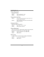
Peripheral Configuration

Serial Port A

 This allows users to configure serial prot A  by using this option.

Disabled

 Disable the configuration.

Enabled

 Enable the configuration (Default value)


Base I/O Address/IRQ

3F8/IRQ4

Set IO address to 3F8.    (Default value)

2F8/IRQ3

Set IO address to 2F8.

3E8/IRQ4

Set IO address to 3E8.

2E8/IRQ3

Set IO address to 2E8.

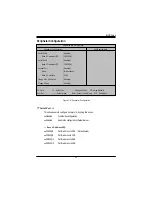
Figure 2-4: Peripheral Configuration

PhoenixBIOS Setup Utility

Peripheral Configuration

Item Specific Help

Serial Port A

[Enabled]

Base I/O address/IRQ

[3F8/IRQ4]

Serial Port B

[Enabled]

Base I/O address/IRQ

[2F8/IRQ3]

Parallel Port

[Enabled]

Mode

[Bi-directional]

Base I/O addreee

[378]

Floppy disk  controller

[Enabled]

Floppy Check

[Enabled]

 F1: Help

KL

: Select Item

+ -: Change Values

F9: Setup Defaults

 Esc: Exit

IJ

: Select Menu

Enter: Select Sub-Menu

F10: Save&Exit

Содержание GS-SR195H

Страница 1: ...System Installation Guide GS SR195H 1U Rack Mount Server Intel Pentium Xeon Processor Serverboard Rev 1 0 25A080 095H0 F00 ...

Страница 2: ...Step 2 4 Memory Installation 14 Step 2 5 PCI Expansion Card Installation 15 Step 2 6 Hard Disk Drive Installation 16 Step 2 7 ZCR Installation and Removal Optional Device 17 Chapter 3 Appearance of GS SR195H 18 3 1 Front View of GS SR195H 18 3 2 Rear View of GS SR195H 19 3 3 Switch and LED Indicators Introduction 20 3 4 LAN LED Description 21 3 5 Connector Icon Description 22 Chapter 4 Motherboard...

Страница 3: ... Setup 28 Main 30 Advanced 33 PCI Configuration 34 Advanced Chipset Control 36 Advanced Processor Options 38 Peripheral Configuration 40 Security 45 Console Redirection 47 Server 47 Boot 51 Exit 52 Chapter 6 Appendix 55 6 1 Acronyms 55 ...

Страница 4: ...sageinstructions Do not use this product near water or a heat source Set up the product on a stable work surface or so as to ensure stability of the system Openingsinthecaseareprovidedforventilation Donotblockorcovertheseopenings Makesureyou provide adequate space around the system for ventilation when you set up your work area Never insert objects of any kind into the ventilation openings To avoi...

Страница 5: ...is own expense Properly shielded and grounded cables and connectors must be used in order to meet FCC emission limits Neither the provider nor the manufacturer are responsible for any radio or television interference caused by using other than recommended cables and connectors or by unauthorized changes or modificationstothisequipment Unauthorizedchangesormodificationscouldvoidtheuser sauthorityto...

Страница 6: ...tmentofCommunicationslabelidentifiescertifiedequipment Thiscertification meansthattheequipmentmeetscertaintelecommunicationsnetworkprotective operationalandsafety requirements TheDepartmentdoesnotguaranteetheequipmentwilloperatetotheusersatisfaction Beforeinstallingthisequipment usersensurethatitispermissibletobeconnectedtothefacilitiesofthe localTelecommunicationsCompany Theequipmentmustalsobeins...

Страница 7: ...ading The termination on a loop may consist of any combination of devices subject only to the requirement that the sum of the Load Numbers of all the devices does not exceed 100 for European users only CAUTION Danger of explosion if battery is incorrectly replaced Replace only with the same or equivalent typerecommendedbythemanufacturer Disposeofusedbatteriesaccordingtothe manufacturer sinstructio...

Страница 8: ... pleaseensure thesystemcomponentsarenotdamagedduringtheshipping Using the following checklist to verify the contents If any component is missing or damaged in the system please contact your vendor immediately Computer motherboards and expansion cards contain very delicate Integrated Circuit IC chips To protect them against damage from static electricity you should follow some precautions whenever ...

Страница 9: ...n Multiple Bit Errors Detection AdditionalFeatures DIMM Sparing support support for RASUM fail over to an on line spare DIMM device Expansion Slot 1 riser card supports 2 x PCI X 64 66MHz add on card 1 x PCI E x8 slot optional SCSI Controller Adaptec AIC 7902W chipset supports dual ultra 320 SCSI channels RAID Support Supports RAID 0 1 10 Supports HOST RAID Adaptec ZCR card SO DIMM supports RAID 5...

Страница 10: ...rial ports COM 1 at rear and 1 at front 1 x USB 2 0 dual port connector 1 x VGA connector 2 x RJ45 LAN ports P S 2 Keyboard and Mouse Connectors System BIOS BIOS Type Lincensed Phoenix on 8Mb Flash RAM SpecialFeatures Supportsmultibootfunction Usersettingforhardwaremonitoring Supports PXE ACPI 1 0 Compliant ACPI defined S1 S4 and S5 Server Management Functions Optional BMC Chip NS IPMI 1 5 control...

Страница 11: ...ive Humidity 10 80 operating Humidity at 30o C Safety Regulations FCC CE BSMI CB System Dimention 19 W x 1 73 H x 28 1 D Electrical Power Supply Redundant Power Supply 525W 1 1 Note 1 If you want to purchase USB FDD we suggest MITSUMI as recommended brand 2 The extended lan port is difficult to unplug please handle it carefully ...

Страница 12: ... Protect it from dust humidity and heat Step 2 1 Chassis Removal and Installation Chapter 2 System Hardware Installation Step 2 Step 1 Thumb Screw Step 1 Loosen the thumbscrew from the back of the server Step 2 Push down the indentation located at rear sides of the chassis and slide toward to remove the top cover Step 3 Reverse Step 1 and 2 to replace the chassis cover ...

Страница 13: ...type and speed that are supported by the motherboard Step 1 Step 2 Step1 Raise the locking bar on the socket Step2 Aligning the pins of the processor with the socket insert the processor into the socket Step3 Close the handle completely and finish CPU installation Step 3 Pin1 indicator ...

Страница 14: ...dule can only fit in one direction 2 Insert the DIMM memory module vertically into the DIMM slot Then push it down 3 Close the plastic clip at both edges of theDIMM slots to lock the DIMM module 4 DIMM must be populated in order starting at the farthest slot from the MCH chipset Each logical DIMM must be made of two identical DIMMs having the same device size on each and the same DIMM size 5 Rever...

Страница 15: ...itation Size limitation for PCI E is listed below Heigth 18 73mm max Length 167 65mm max Width 52mm max Step1 Loosen the riser bracket screws Lift the riser bracket slightly then pull it out from the server chassis Step2 Align the expansion card with the guiding groove Slide the expansion card into the slot until the card firmly seats Step3 Align the riser bracket to the system module and push it ...

Страница 16: ...tep 1 Press the release button and pull the blank out of the drive bay Step 2 Slide hard disk into blank and secure it with screws Step 3 Toreplacetheharddriveblank slidetheblankintothebayuntilitlocksintoplace Connectcable and power Step 4 Reverse step 1 2 and 3 to complete the HDD installtion Step 3 ...

Страница 17: ...tional Device Step 1 Aling a ZCR on the module such that the notch on the ZCR exactly match the notches in themodule Step 2 Push the card in untill it clicks Then press down the card vertically Step 3 To remove the ZCR card unlock the ZCR retaining clips Step 1 Step 2 Step 3 ...

Страница 18: ...S SR195H Rack Mount Server 3 1 Front View of GS SR195H Chapter 3 Appearance of GS SR195H M O R D C e p y T m i l S s D E L s e h c t i w S e v i r D y p p o l F e p y T m i l S s D D H I S C S p a w s t o H ...

Страница 19: ...A L 1 r o t c e n n o C d r a o b y e K 2 r o t c e n n o C e s u o M 3 t r o P A G V 4 t r o P M O C 5 t r o P D I 6 s r o t c e n n o C B S U 7 r o t c e n n o C I S C S 8 d r o C r e w o P 9 t o l S r e s i R e l i f o r P w o L d e t i m i L t o l S r e s i R t h g i e H l l u F ...

Страница 20: ...iption Green On Power On Green Blink Sleep S1 Off Power Off S4 Green Blink Hard Disk Drive Access Off No Access and No HDD Fault Blue On Untiselectedforidentification Off Noidentification I D NMI R R E ES SE ET T R R E ES SE ET T B BU U Z ZZ ZE ER R B BU U Z ZZ ZE ER R S ST TO O P P S ST TO O P P Switch LED Indicators Power Reset ID BTN Buzzer Stop ...

Страница 21: ... 4 LAN LED Description Color Condition Description Green ON LAN Link no Access Green BLINK LAN Access OFF Idle Yellow ON 1Gbpsconnection Green ON 100Mbpsconnection OFF 10Mbpsconnection Name LAN Link Activity GbE LAN Speed ...

Страница 22: ...22 GS SR195H Rack Mount Server 3 5 Connector Icon Description n o c I t s e g g u S n o i t p i r c s e D d r a o b y e K A G V e s u o M N A L t r o P l a i r e S B S U ...

Страница 23: ...23 MotherboardLayout 4 1 GA 9IVDPH Motherboard Layout Chapter 4 Motherboard Layout Jumper Setting A B C D E F G H J Q R S T U V W F K L M N O P I ...

Страница 24: ...pulation A CPU 0 M DDRA2 B CPU1 N DDR B2 C Intel MCH E7320 O DDRA3 D ATI R7000M P DDR B3 E Intel 6300ESB Q DDRA4 F Intel 82541 R DDR B4 G Battery S IPMB1 H IT8712F IX T AdaptecAIC 7902W I SCSI2 U PCI X_1 64 66MHz J ATX V PCI E x8 K DDRA1 W SO DIMM Type ZCR Extention Slot L DDR B1 ...

Страница 25: ...R e l g n i S k n a R e l g n i S k n a R l a u D 2 k n a R e l g n i S 2 k n a R l a u D k n a R l a u D k n a R e l g n i S k n a R e l g n i S k n a R e l g n i S 1 k n a R l a u D 3 k n a R l a u D k n a R l a u D k n a R l a u D k n a R e l g n i S k n a R l a u D 4 k n a R l a u D k n a R l a u D k n a R l a u D k n a R l a u D NOTE For DDR 266 DIMM population DIMM must be populated starting...

Страница 26: ...o its default values by this jumper Default value doesn t include the Shunter to prevent from improper use this jumper To clear CMOS temporarily short 1 2 pin 1 2 3 close Normal Default value JP1 Rear USB Wakeup Function 1 1 2 close Clear CMOS 1 1 1 2 close Normal Default 2 3 close Enable USB wake up function ...

Страница 27: ...27 Jumper Setting JP9 Case Open Function Open Disablethisfunction Close Enable Case open function Default ...

Страница 28: ...General help only for Status Page Setup Menu and Option Page Setup Menu F2 Reserved F3 Reserved F4 Reserved F6 Reserved F7 Reserved F8 Reserved F9 LoadtheOptimizedDefaults F10 Save all the CMOS changes only for Main Menu BIOS Setup is an overview of the BIOS Setup Program The program that allows users to modify the basic system configuration This type of information is stored in battery backed CMO...

Страница 29: ...onalfeaturesenabled disabledsetupmenus z z z z z Boot Thissetuppageincludealltheitemsoffirstbootfunctionfeatures z z z z z Exit There are five optionsin this selection Exit Saving Changes Exit Discarding Changes Load Optimal Defaults Load Failsafe Defaults and Discard Changes GETTINGHELP MainMenu Theon linedescriptionofthehighlightedsetupfunctionisdisplayedatthebottomofthescreen Status Page Setup ...

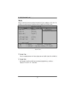
Страница 30: ...ility the Main Menu Figure 1 will appear on the screen Use arrow keys to select among the items and press Enter to accept or enter the sub menu Figure 1 Main PhoenixBIOS Setup Utility Main Advanced Security Server Boot Exit System Time 00 13 12 Item Specific Help System Date 01 01 2005 Lagecy Disktte A 1 44MB 31 2 IDE Channel 0 Master CD ROM IDE Channel 0 Slave None System Information F1 Help KL S...

Страница 31: ...esofharddiskfromdriveCtoFthathasbeeninstalledinthecomputer There are two types auto type and manual type Manual type is user definable Auto type which will automatically detect HDD type Note that the specifications of your drive must match with the drive table The hard disk will not work properly if you enter improper information for this category If you select User Type related information will b...

Страница 32: ...ows if the device type in the specific IDE channel support LBA Mode 32 Bit I O Enable this function to max imize the IDE data transfer rate Transfer Mode ThisfieldshowstheinformationofTeansferMode Ultra DMA Mode This filed displays the DMA mode of the device in the specific IDE channel SystemInformation This category includes the information of Processor Type Speed Extended memory BIOS Version BIO...

Страница 33: ...PhoenixBIOS Setup Utility Main Advanced Security Server Boot Exit PCI Configuration Item Specific Help Advanced Chipset Control Advanced Processor Options Peripheral Configuration Reset Configuration Data No ClkGen Spread Spectrum Disabled System After AC Back Pre State Extended Memory Testing Enabled Network Server Enabled F1 Help KL Select Item Change Values F9 Setup Defaults Esc Exit IJ Select ...

Страница 34: ...unction EmbeddedSCSIController Option ROM Scan Enabled Enableing this item to initialize device expansion ROM Defualtvalue Disabled Disablethisfunction PhoenixBIOS Setup Utility PCI Configuration Item Specific Help Embedded Vedio Controller Embedded SCSI Controller Embedded NIC F1 Help KL Select Item Change Values F9 Setup Defaults Esc Exit IJ Select Menu Enter Select Sub Menu F10 Save Exit ...

Страница 35: ...bit 1 2 Onboard LAN Control Enabled Enable onboard LAN 1 2 device Default value Disabled Disablethisfunction Option ROM Scan Enabled Enableing this item to initialize device expansion ROM Disabled Disablethisfunction Defualtvalue ...

Страница 36: ...ed Enables support for legacy USB Default Value Disabled Disables support for legacy USB Figure 2 2 Advanced Chipset Control PhoenixBIOS Setup Utility Advanced Chipset Control Item Specific Help USB Controller Enabled Legacy USB Support Disabled Force Compliance Mode Enabled PCI E port A Device 2 Enabled 4GB PCI Hole Granularity 128MB Data Parity Error Recovery Enabled Wake On LAN Enabled F1 Help ...

Страница 37: ...d Disables this function 4GBPCIHoleGranularity Select the granularity of PCI hole for PCI resource If MTRRS are not enough we may use this optiontoreducetheMTRRoccupation 128MB Select 128MB as granularity of PCI hole Default value 256MB Select 256MB as granularity of PCI hole Data Parity Error Recovery Enabled Enabledataparityerrorrecoveryfunction Defaultvaules Disabled Disablethisfunction Wake On...

Страница 38: ...gotheroperating systems Machine Checking Enabled EnableMachine Checking Default value Disabled Disablethisfunction PhoenixBIOS Setup Utility Advanced Processor Options Item Specific Help Hyper Threading Technology Enabled Machine Cecking Disabled Thermal Management 2 Disabled Adjacent Cache Line Prefetch Enabled Set Max Ext CPUID 3 Disabled Thermal Management 1 Disabled NX Protection Enabled F1 He...

Страница 39: ...ocessor SetMaxExtCPUID 3 Set MAX CPUID extended function value to 3 Enabled Enable Set Max Ext CPUID 3 function Disabled Disable this function Default value Thermal Managerment 1 If enabled when the thermal sensor indicates that the die temperature is at the pre determined threshold the processor will reduce the bus to core ratio and operating voltage Enabled Enable Thermal Management 1 function D...

Страница 40: ...IRQ4 Set IO address to 3E8 2E8 IRQ3 Set IO address to 2E8 Figure 2 4 Peripheral Configuration PhoenixBIOS Setup Utility Peripheral Configuration Item Specific Help Serial Port A Enabled Base I O address IRQ 3F8 IRQ4 Serial Port B Enabled Base I O address IRQ 2F8 IRQ3 Parallel Port Enabled Mode Bi directional Base I O addreee 378 Floppy disk controller Enabled Floppy Check Enabled F1 Help KL Select...

Страница 41: ...E8 2E8 IRQ3 Set IO address to 2E8 Parallel Port This allows users to configure parallel port by using this option Enabled Enabletheconfiguration Defaultvalue Disabled Disabletheconfiguration Mode This option allows user to set Parallel Port transfer mode EPP Using Parallel port as Enhanced Parallel Port Default Bi directional Usethissettingtosupportbi directionaltransfersontheparallelport ECP Usin...

Страница 42: ...loppy disk controller Enabled Enable the floppy disk controller Default value Disabled Disable the device Floppy Check Enabled Enable the device to verify floppy typer when system boot Disabled Disable the this function Default value ...

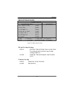
Страница 43: ...ntil the power button is pressed Pre State Set system to the last sate whenAC power is removed Do not power on system when AC power is back Default value Figure 2 Advanced PhoenixBIOS Setup Utility Main Advanced Security Server Boot Exit PCI Configuration Item Specific Help Advanced Chipset Control Advanced Processor Options Peripheral Configuration Reset Configuration Data No ClkGen Spread Spectr...

Страница 44: ... will be performed extended memory above 1M Enabled Enable Extended Memory Testing Default value Disabled Disablethisfunction Network Server Enabled System will be secured at boot to prevent tampering during network operation Defaultvalue Disabled Disablethisfunction ...

Страница 45: ...sword typed now will clear any previously entered password from the CMOS memory You will be asked to confirm the entered password Type the password again and press Enter You may also press Esc to abort the selection and not enter a specified password or press Enter key to disable this option PhoenixBIOS Setup Utility Main Advanced Security Server Boot Exit Supervisor Password Is Clear Item Specifi...

Страница 46: ...p to 6 characters in lengh and press Enter The password typed now will clear any previously entered password from the CMOS memory You will be asked to confirm the entered password Type the password again and press Enter You may also press Esc to abort the selection and not enter a specified password Passwordonboot Password entering will be required when system on boot Enabled Requries entering pas...

Страница 47: ...ear Mem ECC Error Info Disabled Fatal Err on port A Enabled F1 Help KL Select Item Change Values F9 Setup Defaults Esc Exit IJ Select Menu Enter Select Sub Menu F10 Save Exit PhoenixBIOS Setup Utility Console Redirection Item Specific Help Com Port Address Baud Rate 19 2K Console Type Direct Flow Control CTS RTS Continue C R after POST Off IPMI LED Clear Enter F1 Help KL Select Item Change Values ...

Страница 48: ...the standard PC type terminal Note that for VT100 you must select English as your languuage And VT UTF8 uses unicode Options vt100 vt100 vt100 8bit PC ANSI 7bit PC ANSI VT UTF8 FlowControl Enables Flow Control when EMP is dahring the same serial port as console redirection the flow control must be set to CTS RTS or CTS RTS CD depending on whether a modem is used None Notsupported XON OFF Softwarec...

Страница 49: ...r it will stop for all other errors Default value MemoryRASFeatureControl Select specified features for DIMMs Sparing or Memory Mirroring Standard Select Standard as Memory RAS Feature Default value Sparing This feature allows user to uses a spare online bank to provide DIMMfail overcapabilitieswhenapre definedthresholdofsingle bitcorrectableerrorsisreached ClearMem ECCErrorInfo Enabled Enable Cle...

Страница 50: ...er is supplied Power Cycle System powering dowm for 5 seconds than rebooting Triger of CPU reduction This function provide user to select the CPU reduction situation This function is supported when dual CPUs operating IERR Thermal CPU reduction when IERR occuring and system overheating Defaultvalue ThermalTrip CPU reduction when system overheat IERR CPU reduction when IERR occurs Disabled Disablet...

Страница 51: ...wer on Boot Device Priority Removable Device Hard Drive CD ROM Drive These three fields determines which type of device the system attempt to boot from after PhoenixBIOS Post completed Specifies the boot sequence from the available devices If the first device is not a bootable device the system will seek for next available device Figure 5 Boot PhoenixBIOS Setup Utility Main Advanced Security Serve...

Страница 52: ...ar to display the following sub menu Exit Saving Changes Exit Discarding Changes Load Settup Default Discard Change Save Changes PhoenixBIOS Setup Utility Main Advanced Security Server Boot Exit Exit Saving Changes Item Specific Help Exit Discarding Changes Load Settup Default Discard Changes Save Changes F1 Help KL Select Item Change Values F5 Setup Defaults Esc Exit IJ Select Menu Enter Select S...

Страница 53: ...data in CMOS LoadSettupDefault This option allows user to load default values for all setup items When you press Enter on this item you will get a confirmation dialog box with a message as below ExitDiscarding Changes This option allows user to exit system setup without changing any previous settings values in CMOS The previous selection remain in effect This will exit the Setup Utility and restar...

Страница 54: ... get a confirmation dialog box with a message as below Save Changes This option allows user to save setup dat ato CMOS When you press Enter on this item you will get a confirmation dialog box with a message as below Press Yes to save setup daya to CMOS Setup Confirmation Load previous configuration now Yes No Setup Confirmation Save configuration changes now Yes No ...

Страница 55: ...M CNR Communication and Networking Riser DMA Direct Memory Access DMI DesktopManagementInterface DIMM Dual Inline Memory Module DRM DualRetentionMechanism DRAM Dynamic Random Access Memory DDR DoubleDataRate ECP Extended Capabilities Port ESCD Extended System Configuration Data ECC Error Checking and Correcting EMC ElectromagneticCompatibility EPP EnhancedParallelPort ESD ElectrostaticDischarge FD...

Страница 56: ...MTH Memory Translator Hub MPT MemoryProtocolTranslator NIC Network Interface Card OS Operating System OEM OriginalEquipmentManufacturer PAC PCI A G P Controller POST Power On Self Test PCI PeripheralComponentInterconnect RIMM Rambus in line Memory Module SCI SpecialCircumstanceInstructions SECC Single Edge Contact Cartridge SRAM Static RandomAccess Memory SMP Symmetric Multi Processing SMI SystemM...

Отзывы: