


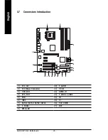


GA-8I915PC Duo Motherboard
- 22 -
English
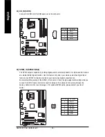
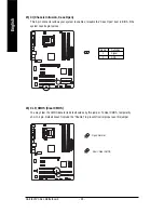
8) F_PANEL (Front Panel Jumper)
Please connect the power LED, PC speaker, reset switch and power switch etc of your chassis front
panel to the F_PANEL connector according to the pin assignment below.
1
2
19
20
HD-
HD+
RES+
RES-
NC
IDE Hard Disk Active LED
Reset Switch
SPEAK-
MSG-
MSG+
PW
-
PW+
Message LED/
Power/
Sleep LED
Speaker Connector
SPEAK+
Power
Switch
HD (IDE Hard Disk Active LED)
Pin 1: LED anode(+)
(Blue)
Pin 2: LED cathode(-)
SPEAK (Speaker Connector)
Pin 1: Power
(Amber)
Pin 2- Pin 3: NC
Pin 4: Data(-)
RES (Reset Switch)
Open: Normal
(Green)
Close: Reset Hardware System
PW (Power Switch)
Open: Normal
(Red)
Close: Power On/Off
MSG(Message LED/Power/Sleep LED)
Pin 1: LED anode(+)
(Yellow)
Pin 2: LED cathode(-)
NC( Purple)
NC
Содержание GA-8I915PC Duo
Страница 1: ...GA 8I915PC Duo Intel Pentium 4 LGA775 Processor Motherboard User s Manual Rev 1001 12ME 8I915PCD 1001 ...
Страница 2: ...Motherboard GA 8I915PC Duo Jan 21 2005 Jan 21 2005 Motherboard GA 8I915PC Duo ...
Страница 8: ... 8 ...
Страница 28: ...GA 8I915PC Duo Motherboard 28 English ...
Страница 52: ...GA 8I915PC Duo Motherboard 52 English ...
Страница 75: ...Appendix 75 English ...
Страница 76: ...GA 8I915PC Duo Motherboard 76 English ...
Страница 77: ...Appendix 77 English ...
Страница 78: ...GA 8I915PC Duo Motherboard 78 English ...