


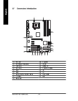


GA-8I915PC Duo Motherboard
- 20 -
English
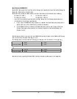
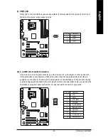
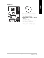
3/4) CPU_FAN / SYS_FAN (Cooler Fan Power Connector)
The cooler fan power connector supplies a +12V power voltage via a 3-pin/4-pin (only for CPU_FAN)
power connector and possesses a foolproof connection design.
Most coolers are designed with color-coded power connector wires. A red power connector wire
indicates a positive connection and requires a +12V power voltage. The black connector wire is
the ground wire (GND).
Please remember to connect the power to the cooler to prevent system overheating and failure.
Caution!
Please remember to connect the power to the CPU fan to prevent CPU overheating and failure.
1
1
CPU_FAN
SYS_FAN
Pin No.
Definition
1
GND
2
+12V
3
Sense
4
Speed Control
(Only for CPU_FAN)
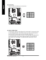
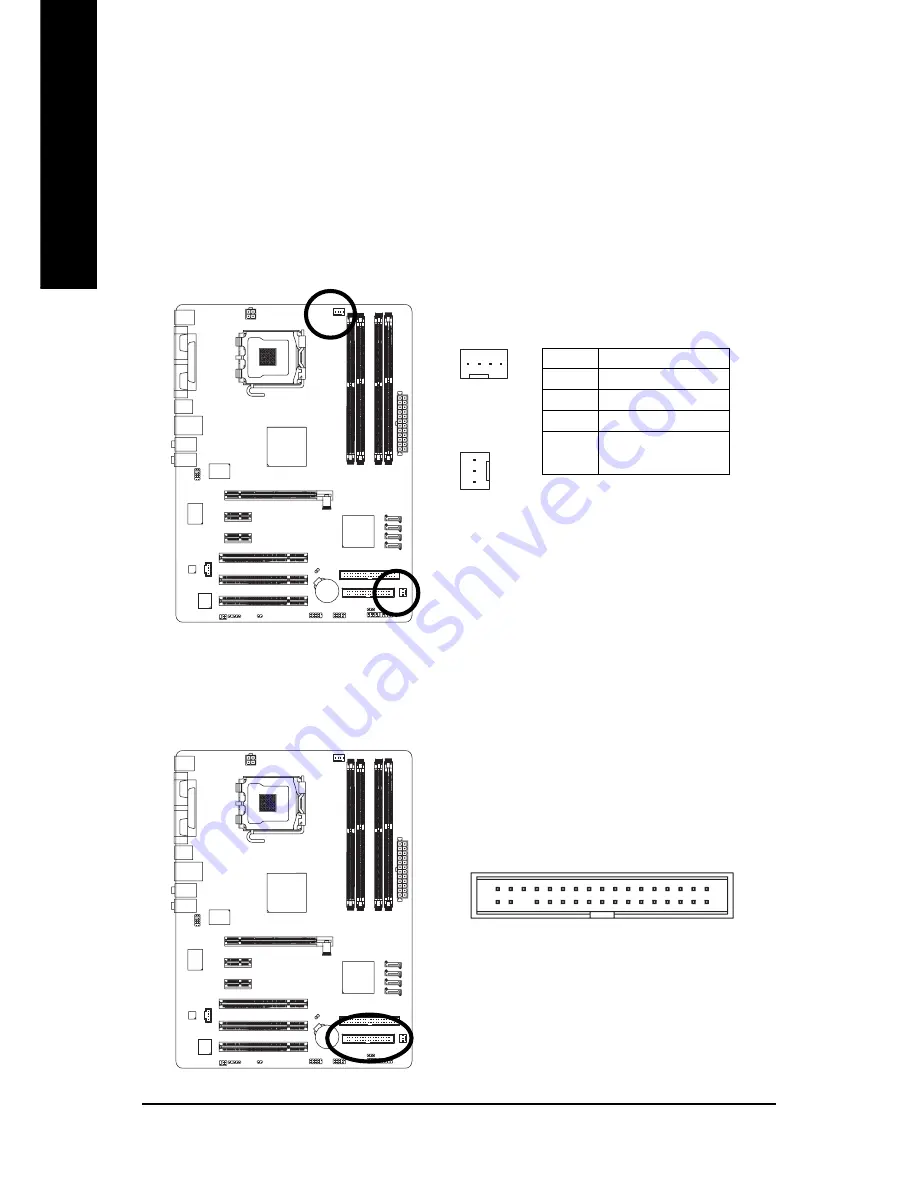
5) FDD (Floppy Connector)
The FDD connector is used to connect the FDD cable while the other end of the cable connects to the
FDD drive. The types of FDD drives supported are: 360KB, 720KB, 1.2MB, 1.44MB and 2.88MB.
Please connect the red power connector wire to the pin1 position.
1
2
33
34
Содержание GA-8I915PC Duo
Страница 1: ...GA 8I915PC Duo Intel Pentium 4 LGA775 Processor Motherboard User s Manual Rev 1001 12ME 8I915PCD 1001 ...
Страница 2: ...Motherboard GA 8I915PC Duo Jan 21 2005 Jan 21 2005 Motherboard GA 8I915PC Duo ...
Страница 8: ... 8 ...
Страница 28: ...GA 8I915PC Duo Motherboard 28 English ...
Страница 52: ...GA 8I915PC Duo Motherboard 52 English ...
Страница 75: ...Appendix 75 English ...
Страница 76: ...GA 8I915PC Duo Motherboard 76 English ...
Страница 77: ...Appendix 77 English ...
Страница 78: ...GA 8I915PC Duo Motherboard 78 English ...