


- 20 -
System Appearance
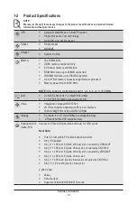
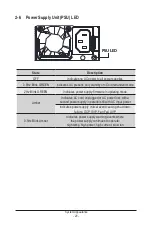
2-6 Power Supply Unit (PSU) LED
PSU LED
State
Description
OFF
Indicates no AC power to all power supplies
0.5Hz Blink GREEN
Indicates AC present/ only standby on/ Cold redundant mode
2Hz Blink GREEN
Indicates power supply firmware in updating mode
Amber
Indicates AC cord unplugged or AC power lost; with a
second power supply in parallel still with AC input power
Indicates power supply critical event causing shut down:
failure, OCP, OVP, Fan Fail, UVP
0.5Hz Blink Amber
Indicates power supply warning events where
the power supply continues to operate:
high temp, high power, high current, slow fan
Содержание G242-P35
Страница 26: ... 26 System Hardware Installation 4 2 3 1 6 ...
Страница 38: ... 38 System Hardware Installation HDD Backplane Board Power Cable GPU2 GPU0 GPU1 GPU3 GPU2 GPU0 GPU1 GPU3 ...
Страница 43: ... 43 System Hardware Installation NVMe Card Cable GPU2 GPU0 GPU1 GPU3 GPU2 GPU0 GPU1 GPU3 ...
Страница 46: ...System Hardware Installation 46 HDD Backplane Board Power Cable GPU1 GPU0 GPU1 GPU0 ...
Страница 48: ...System Hardware Installation 48 GPU Riser Card Power Cable GPU1 GPU0 GPU1 GPU0 ...
Страница 49: ...System Hardware Installation 49 GPU Signal Cable GPU1 GPU0 GPU1 GPU0 ...
Страница 50: ... 50 System Hardware Installation GPU Card Power Cable Reserved GPU1 GPU0 PS ON Signal Cable GPU1 GPU0 ...
Страница 51: ...System Hardware Installation 51 NVMe Card Cable GPU1 GPU0 GPU1 GPU0 ...
Страница 55: ...Motherboard Components 55 This page intentionally left blank ...
Страница 66: ... 66 BIOS Setup 5 2 6 PCI Subsystem Settings ...
Страница 70: ... 70 BIOS Setup 5 2 6 2 PCI Express GEN 2 Settings ...
Страница 80: ... 80 BIOS Setup 5 2 14 Intel R I350 Gigabit Network Connection ...