


- 18 -
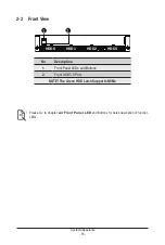
System Appearance
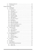
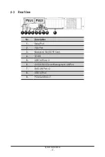
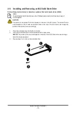
2-4 Front Panel LED and Buttons
L1
L2
2
4
6
1
3
5
7
No. Name
Color
Status
Description
1.
Reset Button
--
--
Press the button to reset the system.
2.
ID Button
Press the button to activate system identification
3.
Power button
with LED
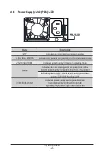
Green
On
Indicates the system is powered on.
Green
Blink
System is in ACPI S1 state (sleep mode).
N/A
Off
• System is not powered on or in ACPI S5 state (power off)
• System is in ACPI S4 state (hibernate mode)
4.
System
Status LED
Green
On
Indicates system is operating normally.
Amber
On
Indicates a critical condition, may include:
-System fan failure
-System temperature issue
Blink
Indicates non-critical condition, may include:
-Redundant power module failure
-Temperature and voltage issue
-Chassis intrusion
N/A
Off
Indicates system is not ready, may include:
-POST error
-Processor or terminator is missing
5.
HDD Status
LED
Green
On
Indicates locating the HDD.
Blink
Indicates accessing the HDD.
Amber
On
Indicates HDD error.
Green/
Amber
Blink
Indicates HDD rebuilding.
N/A
Off
Indicates no HDD access or no HDD error.
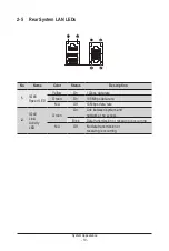
6./7.
LAN 1/2
Active/Link
LEDs
Green
On
Indicates a link between the system and the network or
no access.
Green
Blink
Indicates data trasmission or receiving is occuring.
N/A
Off
Indicates no data transmission or receiving is occuring.
Содержание G242-P35
Страница 26: ... 26 System Hardware Installation 4 2 3 1 6 ...
Страница 38: ... 38 System Hardware Installation HDD Backplane Board Power Cable GPU2 GPU0 GPU1 GPU3 GPU2 GPU0 GPU1 GPU3 ...
Страница 43: ... 43 System Hardware Installation NVMe Card Cable GPU2 GPU0 GPU1 GPU3 GPU2 GPU0 GPU1 GPU3 ...
Страница 46: ...System Hardware Installation 46 HDD Backplane Board Power Cable GPU1 GPU0 GPU1 GPU0 ...
Страница 48: ...System Hardware Installation 48 GPU Riser Card Power Cable GPU1 GPU0 GPU1 GPU0 ...
Страница 49: ...System Hardware Installation 49 GPU Signal Cable GPU1 GPU0 GPU1 GPU0 ...
Страница 50: ... 50 System Hardware Installation GPU Card Power Cable Reserved GPU1 GPU0 PS ON Signal Cable GPU1 GPU0 ...
Страница 51: ...System Hardware Installation 51 NVMe Card Cable GPU1 GPU0 GPU1 GPU0 ...
Страница 55: ...Motherboard Components 55 This page intentionally left blank ...
Страница 66: ... 66 BIOS Setup 5 2 6 PCI Subsystem Settings ...
Страница 70: ... 70 BIOS Setup 5 2 6 2 PCI Express GEN 2 Settings ...
Страница 80: ... 80 BIOS Setup 5 2 14 Intel R I350 Gigabit Network Connection ...