background image

System Hardware Installation

- 30 -

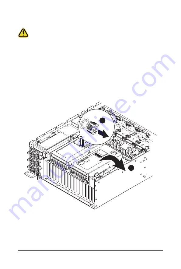
3-5  Installing the PCIe Card

Read the following guidelines before you begin to install the PCIe Card:  

• 

Voltages can be present within the server whenever an AC power source is connected. This 
voltage is present even when the main power switch is in the off position. Ensure that the system 
is powered down and all power sources have been disconnected from the server prior to installing 
a PCIe card. Make sure the system is not turned on or connected to AC power.

• 

Failure to observe these warnings could result in personal injury or damage to the equipment.

Follow these instructions to install the PCIe card:

1.  Pull out the thumbnail screw securing the GPU card cage in place.
2.  Flip over the GPU card cage in the direction indicated.

3.  Remove the two screws securing the PCIe card slot covers in place and remove the PCIe card slot 

covers.

4.  Insert the PCIe card into the selected slot. Make sure the PCIe card is properly seated.

5.  Install the two screws to secure the PCIe card in place.

1

2

Содержание G481-HA1

Страница 1: ...G481 HA0 Dual LGA3647 sockets motherboard for Intel Scalable Family Processors User Manual Rev 1 1 ...

Страница 2: ... and BIOS User Guide detailed information about the installation use of an add on hardware or software component e g BMC firmware rail kit compatible with this product Quick Installation Guide a short guide with visual diagrams that you can reference easily for installation purposes of this product e g motherboard server barebones Please see the support section of the online product page to check ...

Страница 3: ...guide NOTE Gives bits and pieces of additional information related to the current topic CAUTION Gives precautionary measures to avoid possible hardware or software problems WARNING Alerts you to any damage that might result from doing or not doing specific actions ...

Страница 4: ...ticular attention to the plug electrical outlet and the point where the cord extends from the server WARNING To reduce the risk of personal injury from hot surfaces allow the drives and the internal system components to cool before touching them WARNING This server is equipped with high speed fans Keep away from hazardous moving fan blades during servicing CAUTION Do not operate the server for lon...

Страница 5: ...scharge ESD and ESD protection ESD can damage drives boards and other parts We recommend that you perform all procedures in this chapter only at an ESD workstation If one is not available provide some ESD protection by wearing an antistatic wrist strap attached to chassis ground any unpainted metal surface on the server when handling parts ESD and handling boards Always handle boards carefully The...

Страница 6: ...on if battery is replaced incorrectly or with an incorrect type Replace the battery only with the same or equivalent type recommended by the manufacturer Dispose of used bat teries according to the manufacturer s instructions ...

Страница 7: ...oving and Installing the Air Duct 25 3 3 Removing the GPU Fan Module 26 3 4 Installing the GPU Card Optional 27 3 5 Installing the PCIe Card 30 3 6 Installing the CPU and Heat Sink 32 3 7 Installing the Memory 34 3 7 1 Six Channel Memory Configuration 34 3 7 2 Installing a Memory 35 3 7 3 DIMM Population Rule 35 3 7 4 DIMM Population Table 36 3 7 5 Intel Optane DCPMM DIMM Population Rule 37 3 8 In...

Страница 8: ...1 5 2 5 Intel R Omni Path HFI 100 Series 64 5 2 6 Intel R Ethernet Controller X550 66 5 2 7 LSI SAS3 MPT Controller SAS3008 68 5 2 8 Trusted Computing 69 5 2 9 Serial Port Console Redirection 70 5 2 10 SIO Configuration 73 5 2 11 PCI Subsystem Settings 74 5 2 12 Network Stack Configuration 76 5 2 13 Post Report Configuration 77 5 2 14 NVMe Configuration 78 5 2 15 USB Configuration 79 5 2 16 Chipse...

Страница 9: ...iorities 113 5 6 2 UEFI Application Boot Priorities 114 5 7 Save Exit Menu 115 5 8 BIOS POST Codes 117 5 8 1 AMI Standard PEI 117 5 8 2 AMI Standard DXE 117 5 8 3 AMI Standard ERROR 119 5 8 4 Intel UPI POST Codes 120 5 8 5 Intel UPI Error Codes 120 5 8 6 Intel MRC POST Codes 121 5 8 7 Intel MRC Error Codes 121 5 8 8 Intel PM POST Codes 122 5 8 9 Intel PM POST Codes 122 5 9 BIOS POST Beep code AMI ...

Страница 10: ... 10 This page intentionally left blank ...

Страница 11: ...s dry and first touch a metal object to eliminate static electricity Prior to installing the motherboard please have it on top of an antistatic pad or within an electrostatic shielding container Before unplugging the power supply cable from the motherboard make sure the power supply has been turned off Before turning on the power make sure the power supply voltage has been set according to the loc...

Страница 12: ...3MHz for 2nd Generation Intel Xeon Scalable Processors only 2 Intel Optane DC Persistent Memory for 2nd Generation Intel Xeon Scalable Processors only LAN 2 x 10Gb s BASE T LAN ports Intel X550 AT2 2 x 1Gb s BASE T LAN ports Intel I350 AM2 1 x 10 100 1000 management LAN Expansion Slot 10 x PCIe x16 slot Gen3 x16 for GPGPU card 8x GPGPU supported as standard 10x GPGPU optional 1 x PCIe x16 slot Gen...

Страница 13: ...eband signal 1 x TPM header 1 x HDD back plane board header 1 x IPMB connector 1 x RAID key connector 1 x Clear CMOS jumper Front Panel LED Buttons 1 x NMI button 2 x USB3 0 connector 1 x MLAN connector with LED optional for MLAN at rear side of the system 2 x RJ45 LAN connector with LED 1 x VGA connector 1 x Power button with LED 1 x ID button with LED 1 x HDD activity LED 1 x Reset button 1 x Sy...

Страница 14: ... settings email settings Serial Over LAN vKVM vMedia HTML5 Power Supply 3 x 2200W redundant PSU 80 PLUS Platinum AC Input 2200W 200 240V 12 6A 50 60Hz DC Output 2200W 12V 178 1A 12VSB 3 5A Ambient Temperature Relative Humidity Operating temperature 10 C to 35 C Non operating temperature 40 C to 60 C Operating humidity 8 80 non condensing Non operating humidity 20 95 non condensing System Dimension...

Страница 15: ...I COM ASPEED AST2500 MLAN 10 100 1G PHY 1ch MAC BMC 8 x SATAIII 8 x SATAIII DMI3 x4 Front 2 x USB 3 0 2 x USB 2 0 SPI Flash 32MB PCH Intel C621 Lewisburg VGA Skylake SP LGA 3647 Socket P0 CPU0 Skylake SP LGA 3647 Socket P0 CPU1 DDR4 2DPC 6 Channel DDR4 2DPC 6 Channel 12 x DIMM slots 12 x DIMM slots Rear Base T 2 x10G LAN Intel X550 AT2 TPM Slimline 8i x2 PCIe3 0 x16 for 4 x NVMe Slimline 4i x2 con...

Страница 16: ...Hardware Installation 16 This page intentionally left blank ...

Страница 17: ...D 0 HDD 1 HDD 2 HDD 3 HDD 4 HDD 5 HDD 6 HDD 7 HDD 8 HDD 9 HDD 12 HDD 13 HDD 14 HDD 15 HDD 16 HDD 17 HDD 18 HDD 19 HDD 20 HDD 21 HDD 22 HDD 23 No Description No Description 1 RAID Card Slot 5 USB 3 0 Port x 2 2 Front Panel LEDs and Buttons 6 VGA Port 3 10GbE LAN Port x 2 7 2 5 inch HDD Bay x 10 0 to 9 4 10 100 1000 Server Management LAN Port 8 3 5 inch HDD Bay x 12 12 to 23 ...

Страница 18: ... Rear View PSU 1 PSU 2 PSU 3 1 2 3 4 5 6 No Description No Description 1 GPU Fan Module 4 10 100 1000 Server Management LAN Port 2 PCIe x16 Slot x 8 5 LAN Module 3 10GbE LAN Port x 2 optional 6 Power Supply Unit x 3 PSU 1 to 3 ...

Страница 19: ...stem temperature Blink Indicates non critical condition may include Redundant power module failure Temperature and voltage issue Chassis intrusion N A Off Indicates system is not ready may include POST error NMI error Processor or terminator is missing 4 NMI Button Press this button for the server to generate a NMI to the processor If multiple bit ECC errors occur the server will effectively be ha...

Страница 20: ...ss Blink Data transmission or reception is occurring N A Off No data transmission or reception is occurring 2 5 Rear System LAN LEDs Optional 1 1 2 2 1 2 No Name Color Status Description 1 GbE Speed LED Yellow On 1 Gbps data rate Green On 100 Mbps data rate N A Off 10 Mbps data rate 2 GbE Link Activity LED Green On Link between system and network or no access Blink Data transmission or reception i...

Страница 21: ...king 0 5Hz Power supply warning events where the power supply continues to operate such as high temperature high power high current slot fan 2 7 Hard Disk Drive LEDs 2 5 HDD 3 5 HDD LED 1 LED 2 Reserved LED 1 LED 2 Reserved RAID SKU LED1 Locate Rebuilding HDD Fault HDD Access HDD Present No Access No RAID configuration via HBA ICH RAID configuration via HW RAID Card or SW RAID Card Disk LED LED on...

Страница 22: ...DIMM_P0_C1 DIMM_P0_C0 DIMM_P1_L0 DIMM_P1_L1 DIMM_P1_K0 DIMM_P1_K1 DIMM_P1_J0 DIMM_P1_J1 DIMM_P1_G1 DIMM_P1_G0 DIMM_P1_H1 DIMM_P1_H0 DIMM_P1_I1 DIMM_P1_I0 DIMM_P0_B1 DIMM_P0_B0 DIMM_P0_A1 DIMM_P0_A0 Memory Status LED Color Status Description Off The memory module is operating normally Red On Error DIMM missing ...

Страница 23: ...er you are working inside the system case If possible wear a grounded wrist strap when you are working inside the system case Alternatively discharge any static electricity by touching the bare metal system of the system case or the bare metal body of any other grounded appliance Hold electronic circuit boards by the edges only Do not touch the components on the board unless it is necessary to do ...

Страница 24: ...e system is not turned on or connected to AC power Follow these instructions to remove the top rear cover 1 Remove the single screw securing the cover 2 Loosen the two thumbnail screws securing the top rear cover in place 3 Slide the cover towards the rear and remove the cover in the direction indicated 1 2 2 3 3 ...

Страница 25: ... air duct 2 To install the air duct align the rear edge of air duct with the GPU module brackets ensuring that the arrows on the air duct face the rear of the system as shown in the image below and then push down the air duct into chassis until it firmly seats Before you remove the top rear cover Make sure the system is not turned on or connected to AC power ...

Страница 26: ...sen the two thumbnail screws securing the GPU fan module in place 3 Lift up to remove the GPU fan module from the system 1 2 2 3 Before you remove the GPU fan module Make sure the system is not turned on or connected to AC power Disconnect all necessary cable connections Failure to observe these warnings could result in personal injury or damage to the equipment ...

Страница 27: ...ard is properly seated 5 Install the two screws to secure the GPU card in place 6 Install the three screws to secure the GPU card bracket in place 1 1 1 2 Before you install the GPU card Voltages can be present within the server whenever an AC power source is connected This voltage is present even when the main power switch is in the off position Ensure that the system is powered down and all powe...

Страница 28: ...System Hardware Installation 28 3 4 5 ...

Страница 29: ... 29 System Hardware Installation 6 6 6 ...

Страница 30: ...stalling a PCIe card Make sure the system is not turned on or connected to AC power Failure to observe these warnings could result in personal injury or damage to the equipment Follow these instructions to install the PCIe card 1 Pull out the thumbnail screw securing the GPU card cage in place 2 Flip over the GPU card cage in the direction indicated 3 Remove the two screws securing the PCIe card s...

Страница 31: ... 31 System Hardware Installation 3 5 4 ...

Страница 32: ... Follow these instructions to install the CPU 1 Align the processor to the carrier so that the gold triangle on the processor aligns with the triangle on the carrier and then install the processor into the carrier NOTE Apply thermal compound evenly on the top of the CPU 2 Carefully flip the heatsink over Align the carrier assembly so that the triangle on the carrier aligns with the triangle on the...

Страница 33: ... 33 System Hardware Installation 1 2 3 4 CPU0 CPU1 ...

Страница 34: ..._L0 DIMM_P1_L1 DIMM_P1_K0 DIMM_P1_K1 DIMM_P1_J0 DIMM_P1_J1 DIMM_P1_G1 DIMM_P1_G0 DIMM_P1_H1 DIMM_P1_H0 DIMM_P1_I1 DIMM_P1_I0 DIMM_P0_B1 DIMM_P0_B0 DIMM_P0_A1 DIMM_P0_A0 38 3ULPDU 38 6HFRQGDU Read the following guidelines before you begin to install the memory Make sure that the motherboard supports the memory It is recommended that memory of the same capacity brand speed and chips be used Always t...

Страница 35: ...plastic clip at both edges of the DIMM slots to lock the DIMM module 3 Reverse the installation steps when you want to remove the DIMM module 1 2 2 3 7 3 DIMM Population Rule Be sure to install DDR4 DIMMs on this motherboard The initial DIMMs installed must be installed in the primary CPU CPU0 memory slots first When populating DIMMs into a channel slot numbers having the suffix 0 must be populate...

Страница 36: ...balanced Mode Unbalanced Mode Unbalanced Mode Unbalanced Mode Unbalanced Mode Unbalanced Mode Unbalanced Mode Unbalanced Mode Unbalanced Mode Unbalanced Mode Unbalanced Mode Unbalanced Mode Unbalanced Mode Unbalanced Mode Unbalanced Mode Unbalanced Mode Unbalanced Mode Unbalanced Mode Unbalanced Mode Unbalanced Mode Unbalanced Mode Unbalanced Mode Unbalanced Mode Unbalanced Mode Unbalanced Mode Un...

Страница 37: ...slot A0 the DCPMM must be installed into DIMM slot A1 DIMM_P0_D0 RDIMM Slot DIMM_P0_D1 Intel Optane DCPMM Slot DIMM_P0_E0 RDIMM Slot DIMM_P0_E1 Intel Optane DCPMM Slot DIMM_P0_F0 RDIMM Slot DIMM_P0_F1 Intel Optane DCPMM Slot DIMM_P1_L0 RDIMM Slot DIMM_P1_L1 Intel Optane DCPMM Slot DIMM_P1_K0 RDIMM Slot DIMM_P1_K1 Intel Optane DCPMM Slot DIMM_P1_J0 RDIMM Slot DIMM_P1_J1 Intel Optane DCPMM Slot DIMM...

Страница 38: ... disk drive 1 Press the release button 2 Extend the locking lever 3 Pull the locking lever to remove the HDD tray 4 Slide the hard disk drive into the blank HDD tray 5 Secure the hard drive to the tray with the four screws as shown Do not over tighten the screws Slide the hard drive tray into the bay until it locks in place CAUTION We strongly recommend using enterprise level hard disk drives in t...

Страница 39: ...ne Follow these instructions to install a 3 5 hard disk drive 1 Press the release button 2 Extend the locking lever 3 Pull the locking lever to remove the HDD tray 4 Slide the hard disk drive into the blank HDD tray 5 Slide the hard drive tray into the bay until it locks in place CAUTION We strongly recommend using enterprise level hard disk drives in the Gigabyte server system For more informatio...

Страница 40: ...Disconnect all necessary cable connections Failure to observe these warnings could result in personal injury or damage to the equipment FAN 1 FAN 2 FAN 3 FAN 4 FAN 5 FAN 6 Follow these instructions to replace the system fan module For all system fan modules 1 Grasp the finger slots of the fan module and pull up to remove the fan module 2 Reverse the previous steps to install the replacement fan mo...

Страница 41: ...er Follow these instructions to remove the top front cover 1 Remove the three screws securing the cover 2 Slide the cover towards the rear and remove the cover in the direction indicated 1 1 1 2 2 Skip this section if you are not going to replace the PCIe RAID card ...

Страница 42: ...Disconnect any cables that connect to the PCIe RAID card 2 Loosen the thumbnail screw securing the PCIe RAID card lock in place 3 Extend the PCIe RAID card lock 4 Gently pull the PCIe RAID card in the direction inditcated to disconnect the PCIe RAID 5 Reverse the previous steps to install the replacement PCIe RAID card 2 3 1 ...

Страница 43: ... 43 System Hardware Installation 4 ...

Страница 44: ...r supply in the direction indicated 3 Pull out the power supply using the handle 4 Insert the replacement power supply firmly into the chassis Connect the AC power cord to the replacement power supply 1 3 2 4 CAUTION In order to reduce the risk of injury from electric shock disconnect AC power from the power supply before removing the power supply from the system Please see Section 2 2 Rear View f...

Страница 45: ...Module Follow these instructions to replace the LAN module 1 Press the retaining clip on the right side of the LAN module in the direction indicated 2 Pull out the LAN module using the handle 3 Insert the replacement LAN module firmly into the chassis 1 2 3 ...

Страница 46: ...IMM_P1_G1 DIMM_P1_G0 DIMM_P1_H1 DIMM_P1_H0 DIMM_P1_I1 DIMM_P1_I0 DIMM_P0_B1 DIMM_P0_B0 DIMM_P0_A1 DIMM_P0_A0 38 3ULPDU 38 6HFRQGDU 3 15 2 Motherboard Slimline 8i to PCIe Board DIMM_P0_D0 DIMM_P0_D1 DIMM_P0_E0 DIMM_P0_E1 DIMM_P0_F0 DIMM_P0_F1 DIMM_P0_C1 DIMM_P0_C0 DIMM_P1_L0 DIMM_P1_L1 DIMM_P1_K0 DIMM_P1_K1 DIMM_P1_J0 DIMM_P1_J1 DIMM_P1_G1 DIMM_P1_G0 DIMM_P1_H1 DIMM_P1_H0 DIMM_P1_I1 DIMM_P1_I0 DIMM...

Страница 47: ..._P1_G1 DIMM_P1_G0 DIMM_P1_H1 DIMM_P1_H0 DIMM_P1_I1 DIMM_P1_I0 DIMM_P0_B1 DIMM_P0_B0 DIMM_P0_A1 DIMM_P0_A0 38 3ULPDU 38 6HFRQGDU 3 15 4 MLAN NCSI Signal DIMM_P0_D0 DIMM_P0_D1 DIMM_P0_E0 DIMM_P0_E1 DIMM_P0_F0 DIMM_P0_F1 DIMM_P0_C1 DIMM_P0_C0 DIMM_P1_L0 DIMM_P1_L1 DIMM_P1_K0 DIMM_P1_K1 DIMM_P1_J0 DIMM_P1_J1 DIMM_P1_G1 DIMM_P1_G0 DIMM_P1_H1 DIMM_P1_H0 DIMM_P1_I1 DIMM_P1_I0 DIMM_P0_B1 DIMM_P0_B0 DIMM_P...

Страница 48: ...0 DIMM_P1_L1 DIMM_P1_K0 DIMM_P1_K1 DIMM_P1_J0 DIMM_P1_J1 DIMM_P1_G1 DIMM_P1_G0 DIMM_P1_H1 DIMM_P1_H0 DIMM_P1_I1 DIMM_P1_I0 DIMM_P0_B1 DIMM_P0_B0 DIMM_P0_A1 DIMM_P0_A0 38 3ULPDU 38 6HFRQGDU NVMe 0 1 NVMe 2 3 NVMe 4 5 NVMe 6 7 3 15 6 SATA Connections between HDD Backplane Board and Daughter Board 3 5 HDD Backplane Board 2 5 HDD Backplane Board Daughter Board 1 Daughter Board 2 ...

Страница 49: ...ctor 15 IPMB Connector 16 2 x 15 Pin HDD Back Plane Board Connector 17 Memory Status LED 18 PCIe x8 Slot Gen3 19 Jumpers 20 MLAN NCSI Signal 21 SlimLine 4i Connector Miscellaneous 22 SlimLine 4i Connector SATA3 0 3 23 SlimLine 4i Connector SATA3 4 7 24 Battery Cable Connector 25 Omni Path Connector for CPU0 26 SlimLine 8i Connector PCIe Signal 27 BIOS Flash ROM 28 TPM 29 BMC Flash ROM 30 Omni Path...

Страница 50: ... DIMM_P1_G0 DIMM_P1_H1 DIMM_P1_H0 DIMM_P1_I1 DIMM_P1_I0 DIMM_P0_B1 DIMM_P0_B0 DIMM_P0_A1 DIMM_P0_A0 38 3ULPDU 38 6HFRQGDU 1 2 3 4 5 6 1 2 3 6 4 5 Password Clear BIOS_PWD Default Enable 1 2 3 BIOS Recovery BIOS_RCVR Default Enable 1 2 3 ME Force Update ME_UPDATE Default Enable 1 2 3 ME Recovery ME_RCVR Default Enable 1 2 3 S3 Power On Select S3_MASK Default Enable 1 2 3 Clear CMOS CLR_CMOS Default ...

Страница 51: ... caution Inadequate BIOS flashing may result in system malfunction It is recommended that you not alter the default settings unless you need to to prevent system instability or other unexpected results Inadequately altering the settings may result in system s failure to boot If this occurs try to clear the CMOS values and reset the board to default values Refer to the Exit section in this chapter ...

Страница 52: ...tup menus Security Change set or disable supervisor and user password Configuration supervisor password allows you to restrict access to the system and BIOS Setup A supervisor password allows you to make changes in BIOS Setup A user password only allows you to view the BIOS settings but not to make changes Boot This setup page provides items for configuration of boot sequence Save Exit Save all th...

Страница 53: ... displayed on the bottom line of the Main Menu Submenu Help While in a submenu press F1 to display a help screen General Help of function keys available for the menu Press Esc to exit the help screen Help for each item is in the Item Help block on the right side of the submenu When the system is not stable as usual select the Restore Defaults item to set your system to its defaults The BIOS Setup ...

Страница 54: ...re version information Processor Information CPU 0 Brand String CPU 1 Brand String Max CPU Speed CPU Signature Processor Core Microcode Patch Displays the technical specifications for the installed processor s Platform Information Processor PCH RC Revision Displays the information for the installed platform Memory Information Total Memory Note Displays the total memory size of the installed memory...

Страница 55: ...nboard LAN Information LAN1 MAC Address Note Displays LAN MAC address information LAN2 MAC Address Note Displays LAN MAC address information System Date Sets the date following the weekday month day year format System Time Sets the system time following the hour minute second format ...

Страница 56: ... Setup 56 5 2 Advanced Menu The Advanced menu display submenu options for configuring the function of various hardware components Select a submenu item then press Enter to access the related submenu screen ...

Страница 57: ...Configuration Parameter Description iSCSI Initiator Name Add an Attempt Press Enter to configure advanced items Delete Attempts Press Enter to configure advanced items Change Attempt Order Press Enter to configure advanced items ...

Страница 58: ...BIOS Setup 58 5 2 2 Intel R Virtual RAID on CPU Parameter Description Intel R Virtual RAID on CPU Press Enter to manage Intel Virtual RAID on the CPU ...

Страница 59: ... 59 BIOS Setup 5 2 3 Intel R I350 Gigabit Network Connection ...

Страница 60: ... Press the numeric keys to adjust desired values UEFI Driver Displays the technical specifications for the Network Interface Controller Adapter PBA Displays the technical specifications for the Network Interface Controller Device Name Displays the technical specifications for the Network Interface Controller Chip Type Displays the technical specifications for the Network Interface Controller PCI D...

Страница 61: ... 61 BIOS Setup 5 2 4 VLAN Configuration ...

Страница 62: ...BIOS Setup 62 ...

Страница 63: ...red values The valid range is from 0 to 4094 Priority Sets 802 1Q Priority for a new VLAN or an existing VLAN Press the keys to increase or decrease the desired values The valid range is from 0 to 7 Add VLAN Press Enter to create a new VLAN or update an existing VLAN Configured VLAN List Enable Disable the VLAN Options available Enable Disable Default setting is Disable Remove VLAN Press Enter to ...

Страница 64: ...BIOS Setup 64 5 2 5 Intel R Omni Path HFI 100 Series ...

Страница 65: ...lly UEFI Driver Displays the technical specifications for the Advanced Network Interface Controller Device Name Displays the technical specifications for the Advanced Network Interface Controller PCI Device ID Displays the technical specifications for the Advanced Network Interface Controller PCI Address Displays the technical specifications for the Advanced Network Interface Controller Port GUID ...

Страница 66: ...BIOS Setup 66 5 2 6 Intel R Ethernet Controller X550 ...

Страница 67: ...D Press the numeric keys to adjust desired values UEFI Driver Displays the technical specifications for the Network Interface Controller Adapter PBA Displays the technical specifications for the Network Interface Controller Device Name Displays the technical specifications for the Network Interface Controller Chip Type Displays the technical specifications for the Network Interface Controller PCI ...

Страница 68: ...egacy BIOS Apply Changes Save Controller Events Available File Systems Select to choose an available File System Available Directories Select to choose an available Directories Enter File Name Allows to enter File Name Save Events Advanced Controller Properties Port Configuration Allows the logical grouping of the controller phys into one or more ports Report Device Missing Delay Timer Allows to c...

Страница 69: ...mputing Parameter Description Configuration Security Device Support Enable Disable the TPM support feature Options available Enable Disable Default setting is Enable Current Status Information Displays current TPM status information ...

Страница 70: ...and Management Windows Emergency Management Services EMS Console Redirection Note Selects a COM port for EMS console redirection EMS console redirection allows the user to configure Console Redirection Settings to support Out of Band Serial Port management Options available Enabled Disabled Default setting is Disabled COM1 COM2 Serial LAN Legacy Serial Port for Out of Band EMS Console Redirection ...

Страница 71: ...acket A start bit indicates the beginning The standard setting is 1 stop bit Communication with slow devices may require more than 1 stop bit Options available 1 2 Default setting is 1 Flow Control Flow control can prevent data loss from buffer overflow When sending data if the receiving buffers are full a stop signal can be sent to stop the data flow Once the buffers are empty a start signal can ...

Страница 72: ...VT100 Redirection After BIOS POST Note This item allows user to enable console redirection after OS has loaded Options available Always Enable Boot Loader Default setting is Always Enable Legacy Console Redirection Settings Selects a COM port to display redirection of Legacy OS and Legacy OPROM Messages Options available COM1 COM2 Serial Over LAN Default setting is COM1 Out of Band Mgmt Port Micro...

Страница 73: ...e the serial port settings When set to Disabled displays no configuration for the serial port Options available Enabled Disabled Default setting is Enabled Current Displays the serial port base I O address and IRQ Possible Configures the serial port base I O address and IRQ Use Automatic Settings IO 3F8h IRQ 4 DMA IO 3F8h IRQ 3 4 5 7 9 10 11 12 DMA IO 2F8h IRQ 3 4 5 7 9 10 11 12 DMA IO 3E8h IRQ 3 ...

Страница 74: ...BIOS Setup 74 5 2 11 PCI Subsystem Settings ...

Страница 75: ... the onboard LAN1 LAN2 devices Options available Enabled Disabled Default setting is Enabled Onboard LAN1 LAN2 I O ROM Note Enable Disable the onboard LAN1 LAN2 devices and initializes device expansion ROM Options available Enabled Disabled Default setting is Enabled PCI Devices Common Settings Above 4G Decoding Enable Disable memory mapped I O to 4GB or greater address space Above 4G Decoding Opt...

Страница 76: ...etting is Enabled Ipv4 HTTP Support Note Enable Disable the Ipv4 HTTP feature Options available Enabled Disabled Default setting is Disabled Ipv6 PXE Support Note Enable Disable the Ipv6 PXE feature Options available Enabled Disabled Default setting is Disabled Ipv6 HTTP Support Note Enable Disable the Ipv6 HTTP feature Options available Enabled Disabled Default setting is Disabled PXE boot wait t...

Страница 77: ... Post Report Configuration Parameter Description Post Report Configuration Error Message Report Post Error Message Enable Disable the POST Error Message support Options available Enabled Disabled Default setting is Enabled ...

Страница 78: ...BIOS Setup 78 5 2 14 NVMe Configuration Parameter Description NVMe Configuration Displays the NVMe devices connected to the system ...

Страница 79: ...and off support Options available Enabled Disabled Default setting is Enabled USB Mass Storage Driver Support Note Enable Disable the USB Mass Storage Driver Support Options available Enabled Disabled Default setting is Enabled Port 60 64 Emulation Enables the I O port 60h 64h emulation support This should be enabled for the complete USB Keyboard Legacy support for non USB aware OS Options availab...

Страница 80: ...When set to Power Off the system remains off after power shutdown Options available Last State Power Off Power On The default setting depends on the BMC setting Skip Above 4G Decoding for VGA Enable Disable 64bit capable devices to be decoded in Skip Above 4G Address VGA Space Options available Enabled Disabled Default setting is Disabled P2P Bridge IO Size Sets P2P Bridge IO aligned to the size O...

Страница 81: ...Setup 5 3 Chipset Setup Menu Chipset Setup menu displays submenu options for configuring the function of North Bridge and South Bridge Select a submenu item then press Enter to access the related submenu screen ...

Страница 82: ...BIOS Setup 82 5 3 1 Processor Configuration ...

Страница 83: ...les the Intel Trusted Execution Technology support function Options available Enable Disable Default setting is Disable VMX Vanderpool Technology Enable Disable the Vanderpool Technology This will take effect after rebooting the system Options available Enable Disable Default setting is Enable Enable SMX Enable Disable the Secure Mode Extensions SMX support function Options available Enable Disabl...

Страница 84: ...used to assign mmioh resources Total mmioh space can be up to 32xgranularity Per stack mmioh resource assignments are multiples of the granularity where 1 unit per stack is the default allocation Options available 1G 4G 16G 64G 256G 1024G Default setting is 256G Isoc Mode Options available Auto Enable Disable Default setting is Auto Numa Non Uniform Memory Access Enable Disable Non uniform Memory ...

Страница 85: ...elects the UPI link frequency Options available 9 6GB 10 4GB Auto Default setting is Auto SNC Enable Disable SNC Options available Disable Enable Auto Default setting is Disable Stale AtoS Enable Disable Stale A to S Dir optimization Options available Disable Enable Auto Default setting is Disable LLC dead line alloc Enable Disable LLC dead line alloc Options available Disable Enable Auto Default ...

Страница 86: ...lt setting is Auto Enable ADR Enables the detecting and enabling of ADR Options available Enable Disable Default setting is Enable Legacy ADR Mode Enable Disable the Legacy ADR Mode Options available Enable Disable Default setting is Disable ADR Data Save Mode Data Save Mode for ADR Batterybacked or Type 01 NVDIMM Options available Disable Batterybacked DIMMs NVDIMMs Default setting is NVDIMMs Era...

Страница 87: ... Press Enter to configure advanced items RAS Type Displays the RAS type Static Virtual Lockstep Mode Enable Disable the Static Virtual Lockstep mode Options available Disable Enable Default setting is Disable Mirror Mode Mirror Mode will set entire 1LM 2LM memory in system to be mirrored consequently reducing the memory capacity by half Enables the Mirror Mode will disable the XPT Prefetch Options...

Страница 88: ...ult setting is Enable ACS Control Enable Programs ACS only to Chipset Pcie Root Ports Bridges Disable Programs ACS to all PCIe bridges Default setting is Enable Interrupt Remapping Enable Disable the interrupt remapping support function Options available Enable Disable Default setting is Enable PassThrough DMA Enable Disable the Non Isoch VT_D Engine PassThrough DMA support function Options availa...

Страница 89: ...on Isoch VT_D Engine Coherency support Options available Enable Disable Default setting is Enable Intel VMD technology Press Enter to configure advanced items Intel VMD technology Intel VMD Configuration Enable Disable the Intel VMD support function Options available Enable Disable Default setting is Disable MCTP Enable Disable MCTP Management Component Transport Protocol Options available Enable ...

Страница 90: ...ches both voltage and frequency in tandem between high and low levels in response to processor load Options available Enable Disable Default setting is Enable Turbo Mode When this item is enabled the processor will automatically ramp up the clock speed of 1 2 of its processing cores to improve its performance When this item is disabled the processor will not overclock any of its core Options avail...

Страница 91: ...Disable Default setting is Disable CPU C6 Report Allows you to determine whether to let the CPU enter C6 mode in system halt state When enabled the CPU core frequency and voltage will be reduced during system halt state to decrease power consumption The C6 state is a more enhanced power saving state than C1 Options available Disable Enable Auto Default setting is Auto Enhanced Halt State C1E Note ...

Страница 92: ...d uses alternate performance BIAS input from ENERGY_PERF_BIAS_CONFIG Options available OS Controls EPB BIOS Controls EPB Default setting is OS Controls EPB Energy_PERF_BIAS_CFG mode Selects the Energy Performance Bias Configuration Mode Options available Performance Balanced Performance Balanced Power Power Default setting is Balanced Performance Please note that this item is configurable when Pow...

Страница 93: ...nd cannot be access the RAID setup utility at boot time RAID Mode When set to RAID the SATA controller enables both its RAID and AHCI functions You will be allowed to access the RAID setup utility at boot time Options available AHCI RAID Default setting is AHCI Alternate Device ID on RAID Note 1 Enable Disable Alternate Device ID on RAID mode Options available Enable Disable Default setting is Dis...

Страница 94: ...When set to RAID the SATA controller enables both its RAID and AHCI functions You will be allowed to access the RAID setup utility at boot time Options available AHCI RAID Default setting is AHCI Alternate Device ID on RAID Note 1 Enable Disable Alternate Device ID on RAID mode Options available Enable Disable Default setting is Disabled Please note that this option appears when HDD is in RAID Mod...

Страница 95: ...S Setup 5 3 8 Miscellaneous Configuration Parameter Description Miscellaneous Configuration Active Video Selects the active video type Options available Auto Onboard Device PCIE Device Default setting is Auto ...

Страница 96: ...PCIE Device Default setting is Auto ME Firmware Status 1 2 Displays ME Firmware status information Current State for ME Firmware Displays ME Firmware current status information Error Code for ME Firmware Displays ME Firmware status error code Recovery Cause for ME Firmware Displays ME Firmware recovery cause PTT Support Displays if the system supports the Intel Platform Trust Technology ...

Страница 97: ...ure advanced items WHEA Windows Hardware Error Architecture Support Enable Disable WHEA Support Options available Enable Disable Default setting is Enable Memory Error Enabling Press Enter to configure advanced items Memory Error Enable Disable Memory Error Options available Enable Disable Default setting is Enable Memory Corrected Error Enable Disable Memory Corrected Error Options available Enab...

Страница 98: ...escalates Uncorrectable Recoverable Errors to error pins Options available Enable Disable Default setting is Enable Fatal Error Enable Enables and escalates Fatal Errors to error pins Options available Enable Disable Default setting is Enable SERR Propagation Enable Disable SERR propagation Options available Enable Disable Default setting is Enable PERR Propagation Enable Disable PERR propagation ...

Страница 99: ... processing cores to improve its performance When this item is disabled the processor will not overclock any of its core Options available Enable Disable Default setting is Enable CPU C6 report Allows you to determine whether to let the CPU enter C6 mode in system halt state When enabled the CPU core frequency and voltage will be reduced during system halt state to decrease power consumption The C...

Страница 100: ...cessor Options available Enable Disable Default setting is Disable Adjacent Cache Prefetch When enabled cache lines are fetched in pairs When disabled only the required cache line is fetched Options available Enable Disable Default setting is Enable DCU Streamer Prefetcher Prefetches the next L1 data line based upon multiple loads in same cache line Options available Enable Disable Default setting...

Страница 101: ...set Power Down Default setting is Do Nothing Please note that this item is configurable when FRB 2 Timer is set to Enabled OS Watchdog Timer Enable Disable OS Watchdog Timer function Options available Enabled Disabled Default setting is Disabled OS Wtd Timer Timeout Configure OS Watchdog Timer Options available 5 minutes 10 minutes 15 minutes 20 minutes Default setting is 10 minutes Please note th...

Страница 102: ...Event Log Press Enter to configure advanced items View FRU Information Press Enter to view the advanced items BMC network configuration Press Enter to configure advanced items IPv6 BMC Network Configuration Press Enter to configure advanced items ...

Страница 103: ...sing SEL Choose options for erasing SEL Options available No Yes On next reset Yes On every reset Default setting is No When SEL is Full Choose options for reactions to a full SEL Options available Do Nothing Erase Immediately Default setting is Do Nothing Custom EFI Logging Options Log EFI Status Codes Enable Disable the logging of EFI Status Codes if not already converted to legacy Options avail...

Страница 104: ...U Information The FRU page is a simple display page for basic system ID information as well as System product information Items on this window are non configurable Note The model name will vary depends on the product you purchased ...

Страница 105: ...uration BMC VLAN ID Select to configure BMC VLAN ID The valid range is from 0 to 4094 When set to 0 BMC VLAN ID will be disabled BMC VLAN Priority Select to configure BMC VLAN Priority The valid range is from 0 to 7 When BMC VLAN ID is set to 0 BMC VLAN Priority will not be selected ...

Страница 106: ...mically DHCP Do nothing option will not modify any BMC network parameters during BIOS phase Options available Unspecified Static DynamicBmcDhcp Default setting is DynamicBmcDhcp Station IP address Displays IP Address information Subnet mask Displays Subnet Mask information Please note that the IP address must be in three digitals for example 192 168 000 001 Router IP address Displays the Router IP...

Страница 107: ...any BMC network during BIOS phase Options available Enable Disable Default setting is Enable IPv6 BMC Lan IP Address Source Select to configure LAN channel parameters statically or dynamically by BIOS or BMC Options available Unspecified Static Dynamic Obtained by BMC running DHCP Default setting is Dynamic Obtained by BMC running DHCP IPv6 BMC Lan IP Address Prefix Length Check if the IPv6 BMC LA...

Страница 108: ...ble this field a Administrator Password must first be set A user can only access and modify the System Time System Date and Set User Password fields 5 5 Security Menu The Security menu allows you to safeguard and protect the system from unauthorized use by setting up access passwords Parameter Description Administrator Password Press Enter to configure the administrator password User Password Pres...

Страница 109: ...K is enrolled System mode is User Deployed and CSM function is disabled Options available Enabled Disabled Default setting is Disabled Secure Boot Mode Note Secure Boot requires all the applications that are running during the booting process to be pre signed with valid digital certificates This way the system knows all the files being loaded before Windows loads and gets to the login screen have ...

Страница 110: ...ons available Set New Key Exchange Keys KEK Displays the current status of the Key Exchange Key Database KEK Press Enter to configure a new KEK or load additional KEK from storage devices Options available Set New Append Authorized Signatures DB Displays the current status of the Authorized Signature Database Press Enter to configure a new DB or load additional DB from storage devices Options avai...

Страница 111: ...mber of seconds to wait for setup activation key 65535 0xFFFF means indefinite waiting Press the numeric keys to input the desired values Bootup NumLock State Enable Disable the Bootup NumLock function Options available On Off Default setting is On Quiet Boot Enable Disable showing the logo during POST Options available Enabled Disabled Default setting is Enabled Boot mode select Selects the boot ...

Страница 112: ...ure the boot priority By default the server searches for boot devices in the following sequence 1 Hard drive 2 CD COM DVD drive 3 USB device 4 Network 5 UEFI UEFI Network Drive BBS Priorities Press Enter to configure the boot priority UEFI Application Boot Priorities Press Enter to configure the boot priority ...

Страница 113: ...orities The UEFI network drive BBS priorities submenu allows you to specify the boot device priority from the available UEFI network drives during system boot up BIOS setup will display an error message if the legacy drive s specified is not bootable ...

Страница 114: ...orities The UEFI application boot priorities submenu allows you to specify the boot device priority from the available UEFI applications during system boot up BIOS setup will display an error message if the legacy drive s specified is not bootable ...

Страница 115: ...available Yes No Discard Changes and Exit Discards changes made and exits the BIOS setup Options available Yes No Save Changes and Reset Restarts the system after saving the changes made Options available Yes No Discard Changes and Reset Restarts the system without saving any changes Options available Yes No Save Changes Saves changes made in the BIOS setup Options available Yes No Discard Changes...

Страница 116: ...chips or other kinds of low performance components and you choose to load these settings the system might not function properly Options available Yes No Save as User Defaults Saves the changes made as the user default settings Options available Yes No Restore User Defaults Loads the user default settings for all BIOS setup parameters Options available Yes No Boot Override Press Enter to configure ...

Страница 117: ...CT 0x35 PEI_CPU_SMM_INIT 0x36 PEI_MEM_NB_INIT 0x37 PEI_MEM_SB_INIT 0x3B PEI_DXE_IPL_STARTED 0x4F DXE_CORE_STARTED 0x60 Recovery PEI_RECOVERY_AUTO 0xF0 PEI_RECOVERY_USER 0xF1 PEI_RECOVERY_STARTED 0xF2 PEI_RECOVERY_CAPSULE_FOUND 0xF3 PEI_RECOVERY_CAPSULE_LOADED 0xF4 S3 PEI_S3_STARTED 0xE0 PEI_S3_BOOT_SCRIPT 0xE1 PEI_S3_VIDEO_REPOST 0xE2 PEI_S3_OS_WAKE 0xE3 DXE_CORE_STARTED 0x60 DXE_NVRAM_INIT 0x61 D...

Страница 118: ...CT 0x9C DXE_USB_ENABLE 0x9D DXE_IDE_BEGIN 0xA0 DXE_IDE_RESET 0xA1 DXE_IDE_DETECT 0xA2 DXE_IDE_ENABLE 0xA3 DXE_SCSI_BEGIN 0xA4 DXE_SCSI_RESET 0xA5 DXE_SCSI_DETECT 0xA6 DXE_SCSI_ENABLE 0xA7 DXE_SETUP_VERIFYING_PASSWORD 0xA8 DXE_SETUP_START 0xA9 DXE_SETUP_INPUT_WAIT 0xAB DXE_READY_TO_BOOT 0xAD DXE_LEGACY_BOOT 0xAE DXE_EXIT_BOOT_SERVICES 0xAF RT_SET_VIRTUAL_ADDRESS_MAP_BEGIN 0xB0 RT_SET_VIRTUAL_ADDRES...

Страница 119: ..._MICROCODE 0x59 PEI_CPU_INTERNAL_ERROR 0x5A PEI_CPU_ERROR 0x5A PEI_RESET_NOT_AVAILABLE 0x5B Recovery PEI_RECOVERY_PPI_NOT_FOUND 0xF8 PEI_RECOVERY_NO_CAPSULE 0xF9 PEI_RECOVERY_INVALID_CAPSULE 0xFA S3 Resume PEI_MEMORY_S3_RESUME_FAILED 0xE8 PEI_S3_RESUME_PPI_NOT_FOUND 0xE9 PEI_S3_BOOT_SCRIPT_ERROR 0xEA PEI_S3_OS_WAKE_ERROR 0xEB DXE_CPU_ERROR 0xD0 DXE_NB_ERROR 0xD1 DXE_SB_ERROR 0xD2 DXE_ARCH_PROTOCOL...

Страница 120: ...ocol layer and other Uncore settings 0xAA Transition links to full speed operation 0xAB Phy layer settings 0xAC Link layer settings 0xAD Coherency Settings 0xAE KTIRC is done 0xAF 5 8 4 Intel UPI POST Codes When system BSP tries to setup path for remote sockets or sends a Boot_Go command to remote socket in SetupSbspPathToAllSockets or SyncUpPbspForReset If the remote socket s hasn t checked in as...

Страница 121: ...O Initialization 0xB6 Train DDR 0xB7 Initialize CLTT OLTT 0xB8 Hardware memory test and init 0xB9 Execute memory init 0xBA Program memory map and interleaving 0xBB Program RAS configuration 0xBC Rank margin tool 0xBD MRC is done 0xBF 5 8 7 Intel MRC Error Codes No memory was detected 0xE8 Memory test failure 0xEB Different dimm types are detected installed in the system 0xED Number of HAs found in...

Страница 122: ...y Initialization 0xE0 Pre Link training 0xE1 Start of Gen3 EQ training 0xE2 Start of PState transition init 0xE3 Gen3 parameters override 0xE4 End of IIO Early Initialization 0xE5 Start of IIO Late initialization 0xE6 PCIE port initialization 0xE7 IOAPIC initialization 0xE8 VTD initialization 0xE9 IOAT initialization 0xEA DFX initialization 0xEB NTB initialization 0xEC Security Initialization 0xED...

Страница 123: ... Recovery failed 4 S3 Resume failed 7 Reset PPI is not available of Beeps Description 1 Invalid password 4 Some of the Architectural Protocols are not available 5 No Console Output Devices are found 5 No Console Input Devices are found 6 Flash update is failed 7 Reset protocol is not available 8 Platform PCI resource requirements cannot be met 5 9 BIOS POST Beep code AMI standard 5 9 1 PEI Beep Co...

Страница 124: ... block can be used to restore the BIOS to a working state To restore your BIOS please follow the instructions listed below Recovery Instruction 1 Change xxx ROM to amiboot rom 2 Copy amiboot rom and AFUDOS exe to USB diskette 3 Setting BIOS Recovery jump to enabled status 4 Boot into BIOS recovery 5 Run Proceed with flash update 6 BIOS update ...

Отзывы: