3
Consult the factory for special requirements that
must be met if the pump is to operate beyond
one or more of the limits specified above.
Horsepower Ratings:
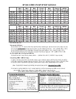
We recommend a 1.15 service factor be specified when selecting an electric motor as the power source.
To compute electric motor horsepower required, use the following formula: HP = (GPM X PSI) / 1450.
The formula to determine the horsepower required for a gas engine is: HP = (GPM X PSI) / 1150.
The formula to determine the horsepower required for a diesel engine is: HP = (GPM X PSI) / 1250.
For the Application of a Hydraulic Motor:
To Determine the Torque of a Hydraulic Motor -- (GPM x PSI x 36.77) / RPM = Torque (in-lbs)
Calculating RPM / GPM of Pump:
A pump must be connected to an electric motor or gas or diesel engine with the correct ratio of pulleys
and belts to attain the required speed and GPM. The use of a Variable Frequency Drive (VFD) may also
be used to control the RPM of a properly sized electric mot
or when variable flows are required.
(Max. Pump RPM / Rated Pump GPM) x Required Pump GPM =
Required Pump RPM
To calculate a pulley diameter one (1) pulley diameter and the required pump RPM must be known:
(Pump RPM x Pump Pulley Diameter) / Motor RPM = Motor Pulley Diameter
(Motor RPM x Motor Pulley Diameter) / Pump RPM = Pump Pulley Diameter
Common Specifications:
Inlet Pressure ..
-4.35 to 145 PSI (-0.3 to 10 Bar)
Max. Temperature ..................140
o
F (60
o
C)
Crankshaft Diameter..............
1.38” (35mm)
Crankcase Oil Capacity .........1.2 Gal. (4.6 L)
Inlet Ports ..............................
(2) 1-1/2” NPT
Discharge Ports .....................
(2) 1” NPT
Stroke ....................................
1.81” (46mm)
Weight ...................................179 lbs (81kg)
Shaft Rotation ..Top of Pulley Toward Fluid End
Materials Used for MP Pumps:
Manifold ........ Nickel-Plated Spheroidal Cast Iron
Plungers ....... Solid Ceramic Oxide
Valves ........... Duplex Steel/Plastic Retainer
Seals............. Nitrile with Fabric Reinforcing
Gear End ...... Spheroidal Cast Iron
GP5100 SERIES PUMP SPECIFICATIONS
Max.
Flow
Max.
Pressure
Max.
Speed
Power
Req’d.
Max.
Temp.
Plunger
Diameter
NPSH
Required
Model
GPM
PSI
RPM
HP
F
in
Ft-Head
GP5132
27.7
2900
1000
57
140
1.26
27.9
GP5132*
40
3000
1444
83
140
1.26
27.9
GP5136
33.8
2320
910
56
140
1.42
27.9
GP5142
40.4
1885
800
54.4
140
1.65
N/A
GP5145
43.5
1450
750
45
140
1.77
29.5
Max.
Flow
Max.
Pressure
Max.
Speed
Power
Req’d.
Max.
Temp.
Plunger
Diameter
NPSH
Required
Model
L/min
Bar
RPM
kW
C
mm
mWs
GP5132
104.9
200
1000
42.8
60
32
8.5
GP5132*
151.4
207
1444
61.9
60
32
8.5
GP5136
127.8
160
910
41.8
60
36
8.5
GP5142
153.0
130
800
40.6
60
42
N/A
GP5145
164.6
100
750
33.6
60
45
9.0
* Intermittent rating
* Intermittent duty only.


