background image


Gianneschi 

Pumps and Blowers

 s.r.l. - Via G. Pastore, n°19/21 

– 55040 Capezzano Pianore (LU) - ITALIA 

 Tel: +39 0584 969391 

 Fax: +39 0584 969411 

Cod. Fisc. e P.Iva IT: 01619620469 

– (REA 154940 Lucca) – Cap. Soc. 54.000 € 

web site: www.gianneschi.net; e-mail: [email protected]


25 


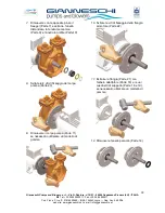
13. Rimuovere il Seeger interno anteriore 

(Parte 15) e il Seeger interno 
posteriore (Parte 20) 


14. 

Estrarre l’albero adattatore (Parte 18) 
con i suoi cuscinetti di supporto (Parte 
16 e 19), se necessario utilizzare un 
martello di gomma 


15. Rimuovere i cuscinetti di supporto 

(Parte 16 e 19)

 
Per il montaggio della elettropompa agire in maniera inversa a come si è smontata, provvedendo a 
sostituire l’anello O-Ring (Parte 5). 
In ogni caso fare sempre riferimento al disegno spaccato della pompa. 
 

ATTENZIONE: 
Le facce lucide della tenuta meccanica e della controfaccia vanno messe a contatto 
Verificare prima del montaggio che le tenute non siano graffiate o danneggiate. 
Pulire accuratamente le sedi della tenuta meccanica 
Pulire accuratamente con alcool le facce di scivolo della tenuta, utilizzare l’alcool per il RI 
assemblaggio della stessa. 


Содержание ACB 531 Series

Страница 1: ...POMPE AUTOADESCANTI SELF PRIMING ELECTRO PUMP ACB 531 MANUALE OPERATIVO DELLE POMPE CENTRIFUGHE AUTOADESCANTI OPERATING MANUAL FOR CENTRIFUGAL SELF PRIMING PUMPS ACB 531 A ACB 531 B ACB 531 C Ed 04 2011 ...

Страница 2: ...N 3 1 4 SAFETY 5 1 5 INSTALLATION 5 1 6 ELECTRICAL CONNECTION 7 1 7 STARTING 7 1 8 MAINTENANCE 8 1 8 1 MECHANICAL SEAL 8 1 9 SPARE PARTS 9 1 9 1 SOBSTITUTION OF THE IMPELLER MECHANICAL SEAL AND BEARINGS 11 INDICE 2 0 INTRODUZIONE 15 2 1 CONDIZIONI DI IMPIEGO 15 2 2 CONTROLLI PRELIMINARI 15 2 3 STOCCAGGIO 15 2 4 SICUREZZA 17 2 5 COLLEGAMENTI ELETTRICI 17 2 6 INSTALLAZIONE E AVVIAMENTO 18 2 7 MANUTE...

Страница 3: ...aused by improper use of the pump 1 1 CONDITION OF USE These el pumps must be used with clean liquids in this conditions Max pressure admitted in the pump casing 8 Bar Max suction depth 8m Temperature of the liquid from 5 C to 60 C Acustic level 85 dB Pump abrasive liquids Not admitted 1 2 PRELIMINARY INSPECTION Unpack the pump and check its integrity Furthermore check that the data on the plate c...

Страница 4: ...ia G Pastore n 19 21 55040 Capezzano Pianore LU ITALIA Tel 39 0584 969391 Fax 39 0584 969411 Cod Fisc e P Iva IT 01619620469 REA 154940 Lucca Cap Soc 54 000 web site www gianneschi net e mail info gianneschi net 4 Fig 1 Example of Lifting ...

Страница 5: ...and clean surface in horizontal position feet down To reduce vibration block the machine with the bolts to the surface and install some vibration dumpers Pipes Install the pipes well anchored on their own supports near the inlet and outlet points of the pump to avoid their transmitting any vibration Ensure the pipes are fully sealed with jointing compound to the pump ports From internal diameter o...

Страница 6: ...wers s r l Via G Pastore n 19 21 55040 Capezzano Pianore LU ITALIA Tel 39 0584 969391 Fax 39 0584 969411 Cod Fisc e P Iva IT 01619620469 REA 154940 Lucca Cap Soc 54 000 web site www gianneschi net e mail info gianneschi net 6 ...

Страница 7: ...e motor and mechanical overloads to the pump Be sure to replace all safety guards before switching on the electrical power If possible check the direction of rotation before the motor is coupled to the pump but protect the motor shaft to prevent any accidents When this is not possible briefly jog the pump to check its direction of rotation see arrow on pump for correct rotation If the direction mu...

Страница 8: ...ever works dry If the pump does not work for a long time it is better to empty the pump casing and clean it If a filter and a foot valve are installed check periodically their integrity and cleanness The impeller never can t blocked If it happens a descaling of the impeller and casing pump must be done 1 8 1 MECHANICAL SEAL Purpose of mechanical seals is to retain handled product inside the pump i...

Страница 9: ...RTS 1 Screw for cover fixing 2 Pump cover 3 Impeller 4 Screw for internal disk 5 O Ring 6 Internal disk 7 Seeger 8 Spacer 9 Mechanical seal 10 Counter face 11 Body pump 12 Washer 13 Priming Cap 14 Oil Seal 15 Seeger 16 Front bearing 17 Adapter shaft key 18 Adapter shaft 19 Back bearing 20 Seeger 21 Connection flange 22 Flange Pump fixing screw 23 Flange Motor fixing screw 24 Motor key 25 Electric ...

Страница 10: ...ia G Pastore n 19 21 55040 Capezzano Pianore LU ITALIA Tel 39 0584 969391 Fax 39 0584 969411 Cod Fisc e P Iva IT 01619620469 REA 154940 Lucca Cap Soc 54 000 web site www gianneschi net e mail info gianneschi net 10 1 9 1 EXPLODED DRAWING ...

Страница 11: ...i net e mail info gianneschi net 11 1 9 1 SOBSTITUTION OF THE IMPELLER MECHANICAL SEAL AND BEARINGS 1 Unscrew the 6 screw of the body pump with the front cup 2 Take the front cup Part 2 3 Extract the Impeller Part 3 and the Impeller Key Part 17 4 Unscrew the 2 internal M6 screw Part 4 5 Tighten two M8 screw to allowed the internal disk extraction 6 Extract the internal disk Part 6 please attention...

Страница 12: ...i net 12 7 Remove the Seeger Part 7 the spacer and the mechanical seal Part 9 with its graphite ring Part 10 8 Unscrew the 4 body pump screw Part 23 9 Remove the body pump Part 11 if it s necessary using the rubber hammer 10 Unscrew the 4 screw for fixing the flange to the motor Part 22 11 Extract the flange Part 21 with the shaft Part 18 and the bearing Part 16 and 19 if it s necessary using the ...

Страница 13: ...ont Part 15 and back Seeger Part 20 14 Extract the shaft Part 18 with the bearings Part 16 and 19 if it s necessary using the rubber hammer 15 Remove the bearings Part 16 and 19 To reassemble all the pumps is better to work in the reverse system changing the O Ring Part 5 ATTENTION The honed faces of the mechanical seal must be at contact Clean Accurately all seals of mechanical seal Lube with gly...

Страница 14: ... detective Consult a Gianneschi Service or dealer The motor run but the pump not work Valve and filter dirty Clean valve and filter Suction depth to height Install the pump neas the water static level Air in suction Check the air tightness of the pipe The pump was not fill up with water Fill up the pump Wrong direction of rotation Invert two polarity The pump make noise Air in the pipes Put out th...

Страница 15: ...so di incidente dovuto a negligenza o alla mancata osservanza delle istruzioni di seguito descritte declina altresì ogni responsabilità per danni causati da un uso improprio del prodotto 2 1 CONDIZIONI DI IMPIEGO Queste elettropompe devono essere utilizzate con liquidi puliti entro queste condizioni Pressione statica massima ammessa nel corpo pompa 8 Bar Massima profondità di aspirazione 8 Mt Temp...

Страница 16: ...con un liquido protettivo idoneo per tutti i componenti della pompa avendo cura di evitare il formarsi di sacche d aria chiudere ogni foro ed apertura che comunica con l interno della pompa proteggere tutte le parti esterne lavorate con prodotti antiruggine ricoprire la pompa con un telo di materiale impermeabile almeno ogni mese far ruotare per alcuni giri la parte rotante dell albero della pompa...

Страница 17: ... elettrici motore della pompa centrifuga ed eventuali accessori collegati siano protetti contro il sovraccarico con opportuni interruttori e o fusibili L intensità di corrente a pieno carico stampata sulla targhetta del motore deve essere usata per selezionare l adeguato grado di protezione E consigliabile prevedere un pulsante di emergenza in posizione agevole nei pressi della pompa Prima di effe...

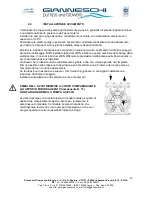
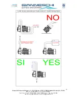
Страница 18: ...are tubazioni di DN inferiore a quello nominale delle flange della elettropompa in caso di tubazioni di DN differente le prestazioni della pompa potrebbero variare a seconda della tubazione installata Verificare che le tubazioni siano correttamente sigillate e che non vi siano perdite nell impianto NB una perdita nella tubazione di aspirazione può far entrare aria all interno del corpo pompa e com...

Страница 19: ...wers s r l Via G Pastore n 19 21 55040 Capezzano Pianore LU ITALIA Tel 39 0584 969391 Fax 39 0584 969411 Cod Fisc e P Iva IT 01619620469 REA 154940 Lucca Cap Soc 54 000 web site www gianneschi net e mail info gianneschi net 19 ...

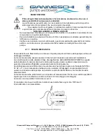
Страница 20: ...nni al motore elettrico se ciò avvenisse provvedere alla disincrostazione della girante e del corpo pompa 2 7 1 TENUTA MECCANICA Scopo delle Tenute Meccaniche è contenere il liquido pompato all interno della pompa nell area di passaggio dell albero Le tenute meccaniche possono essere di diversi tipi di materiali esecuzioni ed installazioni La corretta scelta è stata valutata in fase di progettazio...

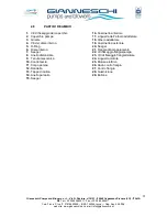
Страница 21: ...mpa 3 Girante 4 Viti del disco interno 5 O Ring 6 Disco interno 7 Seeger 8 Anello distanziale 9 Tenuta meccanica 10 Controfaccia 11 Corpo pompa 12 Rondella 13 Tappo di carica 14 Anello paraolio 15 Seeger 16 Cuscinetto anteriore 17 Linguetta dell albero adattatore 18 Albero adattatore 19 Cuscinetto posteriore 20 Seeger 21 Flangia di accoppiamento 22 Viti fissaggio flangia pompa 23 Viti di fissaggio...

Страница 22: ...Via G Pastore n 19 21 55040 Capezzano Pianore LU ITALIA Tel 39 0584 969391 Fax 39 0584 969411 Cod Fisc e P Iva IT 01619620469 REA 154940 Lucca Cap Soc 54 000 web site www gianneschi net e mail info gianneschi net 22 2 8 1 DISEGNO ESPLOSO ...

Страница 23: ...chi net 23 2 8 2 SOSTITUZIONE DELLA GIRANTE DELLA TENUTA MECCANICA E DEI CUSCINETTI 1 Svitare le 6 viti di fissaggio del coperchio 2 Estrarre il coperchio Parte 2 3 Estrarre la girante Parte 3 e la linguetta dell albero adattatore Parte 17 4 Svitare le 2 viti M6 di fissaggio del disco interno Parte 4 5 Avvitare 2 viti M8 per facilitare l estrazione del disco interno 6 Estrarre il disco interno Par...

Страница 24: ...arte 7 e estrarre l anello distanziale la tenuta meccanica Parte 9 e l anello in grafite Parte10 8 Svitate le 4 viti di fissaggio del corpo pompa Parte 23 9 Rimuovere il corpo pompa Parte 11 se necessario utilizzare un martello di gomma 10 Svitare le viti di fissaggio della flangia al motore Parte 22 11 Estrarre la flangia Parte 21 con l albero adattatore Parte 18 e i suoi cuscinetti di supporto P...

Страница 25: ...essario utilizzare un martello di gomma 15 Rimuovere i cuscinetti di supporto Parte 16 e 19 Per il montaggio della elettropompa agire in maniera inversa a come si è smontata provvedendo a sostituire l anello O Ring Parte 5 In ogni caso fare sempre riferimento al disegno spaccato della pompa ATTENZIONE Le facce lucide della tenuta meccanica e della controfaccia vanno messe a contatto Verificare pri...

Страница 26: ...ianneschi service o ad un rivenditore Il motore gira senza pompare Valvole e filtri ostruiti Pulire valvola e filtro Altezza di aspirazione eccessiva Avvicinare la pompa al livello static del liquido Aria in aspirazione Verificare la tenuta del tubo di aspirazione La pompa non è stata innsecata al primo avviamento Riempire il corpo pompa di liquido Errato senso di rotazione Invertire le fasi del m...

Страница 27: ...to di questa dichiarazione prima che l impianto o il sistema in cui sarà incorporato sia stato dichiarato conforme alle disposizioni delle direttive vigenti e ai regolamenti di classe applicabili Dichiara inoltre che la marcatura è apposta sulla targhetta del prodotto DECLATATION OF CONFORMITY Under Annex II of the Machinery Directive 2006 42 CE as amended The undersigned manufacturer GIANNESCHI P...

Страница 28: ... Cod Fisc e P Iva IT 01619620469 REA 154940 Lucca Cap Soc 54 000 web site www gianneschi net e mail info gianneschi net 28 ________________________ASSISTENZA SERVICE_______________________ GIANNESCHI SERVICE srl Via dei Calzolai 2 b 55041 Capezzano Pianore LU ITALY Tel 39 0584 361087 r a Fax 39 0584 361088 service gianneschi net ...

Отзывы: