SECULOGIC T 320
12
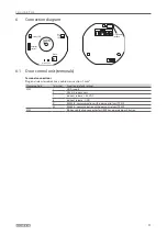
Connection diagram
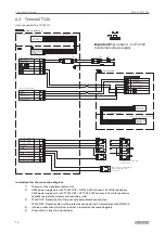
6.2 Terminal T 320
Here connected to a TZ 320 SN.
Important!
Set jumper 1-2 of TZ 320
to external voltage supply.
3)
1)
2)
4)
5)
GEZE Key-operated push button
GEZE ribbon cable
Connection to
TST 320 X 102
Plug connector for
GEZE key-operated
push button or
illumination
X104 (red terminal strip)
GND supply
24 V DC supply
Power supply unit
Luster terminal
Door terminal
GND supply
24 V DC supply
Indirect r
Indirect release -
Connection to
GEZE SCT 320
Plug connector for
GEZE key-operated
push button or
illumination
X107 (green terminal strip)
indirect release
indirect release
GEZE Key-operated push button SCT 320
GEZE ribbon cable
Short-term unlock via push button,
key-operated push button,
access control...
Caution! Disconnect red bridge
(1-7) in FTÖ 331U.
or
Door contact
X106 (orange terminal strip)
Locking mec
Locking mechanism -
Door locked
24 V DC
Door closed
24 V DC
Input 1 (short-term unlock)
Input 2 (short-term unlock)
Input 3 (Fire alarm system)
24 V DC
GND
Door control unit
Instructions for the connection diagram
1)
The mains fuse is implemented on-site.
2) GEZE power supply unit with TZ 320N UP = NET220. 500 mA max. 350 mA for periphery
GEZE power supply unit with TZ 320N AP = NT19.2-24. 750 mA max. 650 mA for periphery
Spatially separate the primary and secondary sides.
3) TZ 320N UP: Protection class II (do not connect protective conductor)
TZ 320N AP: Protection class I with protective conductor test in accordance with VDE0100
4) In the on-wall variant, the luster terminal is located on the mounting plate.
5) The contact is closed in a closed door.


