background image

23 


I

NSTALLAZIONE


V

ERSIONE RACK


Di seguito viene descritta la sequenza di operazioni da seguire per trasformare l’UPS in versione rack. 

ATTENZIONE: per la Vostra sicurezza e del Vostro prodotto, è necessario seguire scrupolosamente le 
informazioni riportate qui di seguito. 


PRIMA DI EFFETTUARE LA SEGUENTE SEQUENZA DI OPERAZIONI, 

ASSICURARSI CHE L’UPS SIA COMPLETAMENTE SPENTO E PRIVO DI 

COLLEGAMENTO ALLA RETE ELETTRICA E A QUALSIASI CARICO 
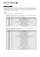


1 -


Per prima cosa è necessario smontare i 4 
piedini sul fondo dell’UPS. Portare l’UPS 
in posizione orizzontale prestando la 
massima cautela e con un piccolo 
cacciavite a taglio sollevare delicatamente 
il perno posto al centro del piedino. Una 
volta sollevato, sfilare il piedino dalla base 
dell’UPS. Ripetere le stesse operazioni per 
tutti i piedini rimanenti. A lato viene 
illustrata l’esatta sequenza da seguire: 
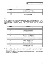
 

2 -


Smontati tutti i piedini, si deve procedere a ruotare la maschera display. 
Infilare le chiavette in dotazione nelle feritoie di sgancio che si trovano 
ai lati della maschera display ed esercitare una leggera pressione quanto 
basta per sganciare la maschera dall’UPS, come evidenziato nella figura 
a lato. 


3 -


ATTENZIONE: La maschera display è collegata all’UPS tramite apposito cavo. E’ necessario quindi 
estrarre la maschera con estrema cautela evitando violenti strappi o altri moviventi bruschi, onde 
evitare possibili danni al display e/o all’UPS stesso. NON TENTARE IN NESSUN MODO DI 
SEPARARE LA MASCHERA DISPLAY DALL’UPS. 

4 -


Ruotare la maschera di 90° in senso antiorario e riagganciarla all’UPS inserendola delicatamente 
nell’apposito alloggio fino ad udire un leggero scatto con la maschera che rimane in posizione. 

5 -


Ruotare l’UPS di 90° in senso orario prestando la massima cautela. 
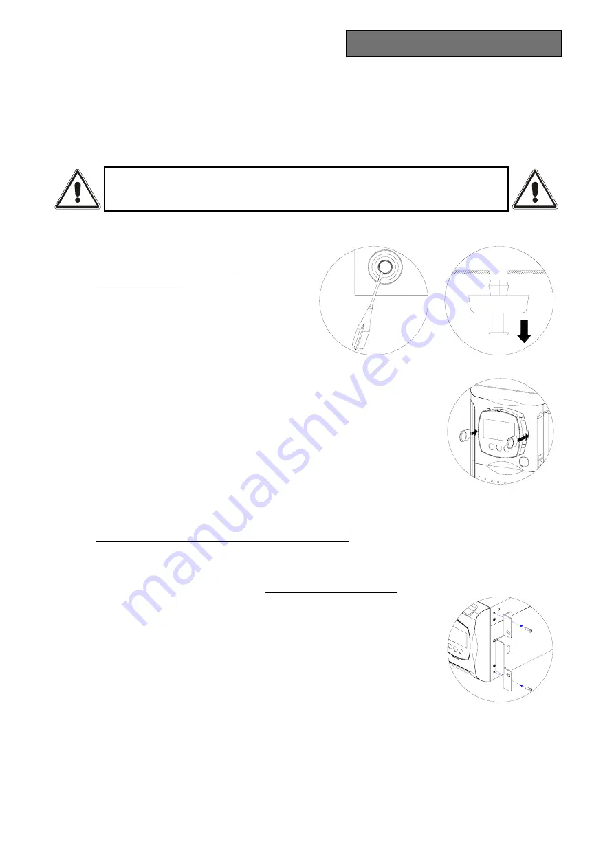
 

6 -


A questo punto, con l’UPS in posizione orizzontale, fissare le maniglie ai 
lati dell’UPS tramite le viti apposite come mostrato nella figura a lato. 
(maniglie e viti sono incluse nel 

kit maniglie 

opzionale) 


NOTE: 

L’UPS è compatibile al montaggio in armadi rack standard 600mm x 800mm o superiore (in 

profondità). Nell’installazione rack dato il peso dell’UPS è obbligatorio l’utilizzo delle staffe di 
sostegno (guida con supporto a L). Sempre per lo stesso motivo, è consigliabile installare l’UPS 
nella parte bassa dell’armadio rack. 

1

2

Содержание 3300 VA

Страница 1: ...Uninterruptible Power Supply ON LINE MULTISTANDARD 3300 VA 4000 VA Manuale d uso User s Manual Bedienungsanleitung Manuel d utilisateur Manual de Usuario...

Страница 2: ......

Страница 3: ...I MANUALE D USO 15 SAFETY 6 GB USER S MANUAL 41 SICHERHEIT 7 D BEDIENUNGSANLEITUNG 67 S CURIT 8 F MANUEL D UTILISATEUR 93 SEGURIDAD 9 E MANUAL DE USUARIO 119 GR 10 S S KERHETEN 11 NL VEILIGHEID 12 P...

Страница 4: ...4...

Страница 5: ...UPS h Il cavo di alimentazione separabile inteso come dispositivo di sezionamento Aver cura di lasciar libero uno spazio adeguato sul retro dell UPS in prossimit del collegamento del cavo per un facil...

Страница 6: ...e UPS h The detachable power cord can be considered to be a sectioning device Make sure to leave enough free space at the rear of the UPS in the vicinity of the cable connection point for easy disconn...

Страница 7: ...in die USV eintreten h Das trennbare Versorgungskabel ist als Trennvorrichtung zu verstehen Es ist zu beachten dass ein angemessener Freiraum auf der R ckseite der USV in der N he des Kabelanschlusse...

Страница 8: ...ble d alimentation s parable est consid r comme un dispositif de sectionnement Laisser toujours un espace libre appropri derri re l ASI proximit du branchement du c ble pour pouvoir le d brancher faci...

Страница 9: ...i n separable tiene por objeto servir de dispositivo de seccionamiento Tener cuidado de dejar un espacio libre adecuado en la parte posterior del SAI cerca de la conexi n del cable para una f cil desc...

Страница 10: ...10 GR GR a UPS UPS b c UPS d UPS UPS e f UPS g UPS h UPS i UPS j UPS 1 mA 3 5 mA 2 5 mA UPS IEC 309 UPS k l T UPS m F UPS 0 1 UPS UPS N N N N N...

Страница 11: ...d f r anv ndning som sektioneringsanordning Se till att ett l mpligt stort fritt utrymme finns p baksidan av UPS i n rheten av kabelanslutningen s att fr nkoppling l tt kan utf ras i Om fara skulle up...

Страница 12: ...at er geen water andere vloeistof en of vreemde voorwerpen in het apparaat binnendringen h De scheidbare voedingskabel dient als sectie inrichting Zorg ervoor dat in de buurt van de kabelaansluiting a...

Страница 13: ...PS h O cabo de alimenta o desconect vel utilizado como dispositivo de corte Ter o cuidado de deixar um espa o livre adequado atr s da UPS perto da conex o do cabo para uma f cil desconex o i Em situa...

Страница 14: ...14...

Страница 15: ...15 I MANUALE D USO I...

Страница 16: ...truzioni dettagliate per l uso e l installazione dell UPS Per informazioni sull utilizzo e per ottenere il massimo delle prestazioni dalla Vostra apparecchiatura il presente manuale dovr essere conser...

Страница 17: ...EGNIMENTO DELL UPS 24 INDICAZIONI PANNELLO DISPLAY 25 Indicatori di stato dell UPS 25 Area visualizzazione misure 26 Area di configurazione 27 MODALIT DI FUNZIONAMENTO 28 CONFIGURAZIONE UPS 29 PORTE D...

Страница 18: ...il prodotto nelle 2 differenti versioni L UPS inoltre dotato di un battery pack dedicato che consente una facile sostituzione delle batterie a caldo hot swap in tutta sicurezza grazie al sistema di co...

Страница 19: ...tore generale Pannello frontale removibile Vista frontale Porta di comunicazione USB Ventole di raffreddamento Connettore espansione batteria Porta di comunicazione RS232 Slot di espansione COMMUNICAT...

Страница 20: ...namento da batteria 4 Carico alimentato da bypass 5 Indicatore autonomia batteria 6 Indicatore livello carico 7 Area di configurazione 8 Richiesta manutenzione 9 Timer 10 Area visualizzazione misure 1...

Страница 21: ...prima cosa procedere alla verifica del contenuto L imballo dovr contenere UPS Cavo di alimentazione spina Schuko presa IEC 16A 2 cavi di collegamento IEC 10A Spina volante IEC 16A 2 cover in plastica...

Страница 22: ...ll imballo l UPS si presenta gi predisposto per l installazione in configurazione tower Per completare tale configurazione basta montare le due cover in plastica in dotazione nella parte superiore del...

Страница 23: ...lay ed esercitare una leggera pressione quanto basta per sganciare la maschera dall UPS come evidenziato nella figura a lato 3 ATTENZIONE La maschera display collegata all UPS tramite apposito cavo E...

Страница 24: ...lo premuto tutte le icone del display si accendono per 1 secondo e l UPS emette un beep 2 Accendere l apparecchiatura collegata all UPS Solo per la prima accensione trascorsi circa 30 sec verificare i...

Страница 25: ...sincronizzata con la tensione di rete Fissa L UPS sta funzionando da batteria Quando si trova in questo stato l UPS emette un segnale acustico beep ad intervalli regolari di 4 sec Lampeggiante Preall...

Страница 26: ...i esempi ESEMPIO GRAFICO 1 DESCRIZIONE Tensione di rete Frequenza di rete Tensione in uscita dall UPS Frequenza della tensione di uscita Autonomia residua delle batterie Percentuale di carica delle ba...

Страница 27: ...no 2 sec La scritta SET si accende e compare una freccia alla sinistra di Frequenza La freccia indica il settaggio selezionato Per cambiare la selezione del parametro da modificare premere il pulsante...

Страница 28: ...l rientro della rete in tolleranza il carico viene nuovamente commutato su bypass Nel caso in cui l utente non sappia decidere la modalit pi adatta di funzionamento tra ON LINE e ECO pu affidare la sc...

Страница 29: ...di ingresso Tensione di uscita Selezione della tensione nominale di uscita 230V 220V 230V 240V 220 240 in step di 1V solo tramite software Modalit di funzionamento Selezione di una delle 4 diverse mo...

Страница 30: ...zione dell uscita 5 0 25 0 5 0 75 1 10 in step di 1 Soglie di tensione bypass Seleziona il range di tensione ammesso per il passaggio su bypass Bassa 180V Alta 264V Bassa 180 200 in step di 1V Alta 25...

Страница 31: ...i alimentazione interfaccia 12Vdc 8 Contatto chiuso preallarme di fine scarica 9 Contatto chiuso funzionamento da batteria Contatto optoisolato max 30Vdc 10mA Communication Slot l UPS fornito di uno s...

Страница 32: ...mazioni pi dettagliate sull installazione ed utilizzo consultare il manuale del software presente nella cartella Manuals del CD Rom in dotazione Per verificare la disponibilit di una versione del soft...

Страница 33: ...unzionamento dell UPS si raccomanda di sostituire il battery pack solamente con UPS acceso 3 Il battery pack collegato al resto dell UPS tramite un cavo con morsetto Facendo riferimento alla figura qu...

Страница 34: ...ODALITA STAND BY Premere il tasto ON posto sul pannello frontale per alimentare i carichi LA MODALITA STAND BY OFF E SELEZIONATA E necessario cambiare la modalit Infatti la modalit STAND BY OFF soccor...

Страница 35: ...MALFUNZIONAMENTO DELL UPS PROBABILE PROSSIMO BLOCCO Se possibile disalimentare il carico spegnere e riaccendere l UPS nel caso il problema si ripresentasse chiamare il centro assistenza IL CICALINO SU...

Страница 36: ...gresso bloccato non apre A54 ON LINE carico della soglia utente ECO carico 16A A61 Batterie da sostituire A62 Battery pack assente o non collegato A63 Attesa ricarica batterie Allarmi sono problemi pi...

Страница 37: ...di temperatura guasto L07 Sensore2 di temperatura guasto L10 Fusibile di ingresso rotto o rel di ingresso bloccato non chiude L13 Precarica condensatori fallita L20 Sottotensione banco condensatori L...

Страница 38: ...Ah 9 12 7 high rate discharge Tempo di ricarica h 4 8 USCITA Tensione nominale 7 Vac 220 230 240 1 5 Variazione statica 3 1 5 Variazione dinamica 4 5 in 20 msec Forma d onda Sinusoidale Distorsione t...

Страница 39: ...di 164 Vac batteria in carica 2 carico nominale tensione nominale di 230 Vac batteria in carica 3 Rete Batteria carico 0 100 4 Rete batteria rete carico resistivo 0 100 0 5 Se la frequenza di rete en...

Страница 40: ...40...

Страница 41: ...41 GB USER S MANUAL GB...

Страница 42: ...how to use and install the UPS For information on using and getting the best performance from your UPS this manual should be kept safely in the vicinity of the UPS and CONSULTED BEFORE TAKING ANY ACT...

Страница 43: ...G ON FROM THE BATTERY 50 SWITCHING THE UPS OFF 50 DISPLAY PANEL INDICATIONS 51 UPS status indicators 51 Measurements display area 52 Configuration area 53 MODES OF OPERATION 54 UPS CONFIGURATION 55 CO...

Страница 44: ...ct versions are shown below The UPS also has a dedicated battery pack that permits easy replacement of the batteries hot swap entirely safely for the operator thanks to the protected connection system...

Страница 45: ...rotatable display mask General switch Removable front panel Front view USB communication port Cooling fans Battery expansion connector RS232 communication port COMMUNICATION SLOT Expansion slot Input...

Страница 46: ...Operating on battery power 4 Load powered from bypass 5 Battery back up indicator 6 Load level indicator 7 Configuration area 8 Maintenance action required 9 Timer 10 Measurements display area 11 Stan...

Страница 47: ...ck the first thing to do is make a check of the contents The pack should contain UPS Power cord Schuko plug IEC 16A socket 2 IEC 10A connection cables IEC 16A spare socket 2 plastic covers top panels...

Страница 48: ...ANY KIND Once removed from its packaging the UPS is already prepared for installation in tower configuration To complete the configuration all that is needed is to fit the two plastic covers provided...

Страница 49: ...mask from the UPS as demonstrated in the drawing on the side 3 WARNING The display mask is connected to the UPS by a special cable This means that you must extract the mask taking extreme care and avo...

Страница 50: ...he icons on the del display light for 1 second and the UPS sounds a beep 2 Switch on the equipment item s connected to the UPS Only when switching on for the first time after about 30 sec have elapsed...

Страница 51: ...ltage Fixed The UPS is working on battery power When in this condition the UPS emits a beep at 4 second regular intervals Blinking End of discharge early warning Indicates that the battery s back up i...

Страница 52: ...ode A number of examples are shown below SAMPLE GRAPHIC 1 DESCRIPTION Mains voltage Mains frequency UPS output voltage Output voltage frequency Remaining battery backup Battery charge percentage SAMPL...

Страница 53: ...for at least 2 sec The word SET lights and an arrow appears to the left of Frequency The arrow indicates the setting selected To change the selection of the parameter to be modified press the SEL SET...

Страница 54: ...g mode About five minutes after the mains has returned inside tolerance the load is again switched to bypass Where a user is unable to decide between the most suitable operating mode ON LINE or ECO he...

Страница 55: ...of the input frequency Output voltage Selects the nominal output voltage 230V 220V 230V 240V 220 240 in steps of 1V only through the software Operating mode Selects one of the 4 different modes of ope...

Страница 56: ...put synchronization 5 0 25 0 5 0 75 1 10 in steps of 1 Bypass voltage thresholds Selects the permitted voltage range for switchover to bypass Low 180V High 264V Low 180 200 in steps of 1V High 250 264...

Страница 57: ...power supply input 8 Contact closed end of discharge early warning 9 Contact closed battery powered operation Optoisolated contact max 30Vdc 10mA Communication Slot The UPS is provided with an expans...

Страница 58: ...nstallation program For more detailed information about installation and use see the software user manual in the Manuals folder of the CD ROM supplied To check if a more up to date version of the soft...

Страница 59: ...mmended that you replace the battery pack only with the UPS switched on 3 The battery pack is connected to the rest of the UPS by means of a cable with terminal See the figure on the side press the 2...

Страница 60: ...he ON button on the front panel to power the loads THE STAND BY OFF MODE IS SELECTED You must change mode STAND BY OFF mode back up powers the loads only when there is a black out THE DISPLAY IS ON BU...

Страница 61: ...2 F43 A UPS MALFUNCTION IS TAKING PLACE SHUTDOWN IMMINENT If it is possible to power down the load switch off the UPS and switch it on again if the problem occurs again contact the service centre THE...

Страница 62: ...ot open A54 ON LINE load of the user threshold ECO load 16A A61 Batteries need replacement A62 Battery pack missing or not connected A63 Waiting for batteries to recharge Alarms these problems are mor...

Страница 63: ...on heat sinks L05 Temperature Sensor1 broken L07 Temperature Sensor2 broken L10 Input fuse broken or input relay stuck does not close L13 Capacitor precharging failure L20 Capacitor bank undervoltage...

Страница 64: ...9 12 7 high rate discharge Recharge time h 4 8 OUTPUT Nominal voltage 7 Vac 220 230 240 1 5 Static variation 3 1 5 Dynamic variation 4 5 in 20 msec Waveform Sinusoidal Voltage distortion linear load...

Страница 65: ...m voltage of 164 Vac battery charging 2 nominal load nominal voltage of 230 Vac battery charging 3 Mains Battery load 0 100 4 Mains battery mains resistive load 0 100 0 5 If the mains frequency is wit...

Страница 66: ...66...

Страница 67: ...67 D BEDIENUNGSANLEITUNG D...

Страница 68: ...andbuch enth lt detaillierte Anweisungen zur Benutzung und Installation der USV Um Informationen ber die Benutzung und die besten Leistungen Ihres Ger ts zu erzielen muss dieses Handbuch mit Sorgfalt...

Страница 69: ...ETRIEB 76 AUSSCHALTEN DER USV 76 ANGABEN AUF DER DISPLAY TAFEL 77 Anzeiger f r den USV Zustand 77 Bereich zur Visualisierung von Messwerten 78 Konfigurationsbereich 79 BETRIEBSART 80 KONFIGURATION DER...

Страница 70: ...das Produkt in den 2 verschiedenen Ausf hrungen dargestellt Ferner ist die USV mit einem zweckbestimmten Batterieblock versehen der dank des gesch tzten Anschlusssystems einen leichten Ersatz der Bat...

Страница 71: ...Displaymaske Hauptschalter Abnehmbare Frontplatte Vorderansicht Kommunikations schnittstelle USB K hll fter Stecker Batterieerwei terung Kommunikations schnittstelle RS232 Erweiterungsslot COMMUNICAT...

Страница 72: ...riebetrieb 4 Durch By pass versorgte Last 5 Batterieautonomie Anzeiger 6 Ladeniveau Anzeiger 7 Konfigurationsbereich 8 Wartungsanforderung 9 Timer 10 Messwertanzeigebereich 11 Bereitschaft stand by Al...

Страница 73: ...rst mit der berpr fung des Inhalts vorgehen Die Verpackung muss beinhalten USV Versorgungskabel Schuko Stecker Steckbuchse IEC 16A 2 Anschlusskabel IEC 10A Fliegender Stecker IEC 16A 2 Plastikabdeckun...

Страница 74: ...zeigt sich die USV bereits vorbereitet f r die Installation in der Turm Konfiguration Zur Vervollst ndigung jener Konfiguration reicht es aus die beiden mitgelieferten Plastikabdeckungen im oberen Te...

Страница 75: ...bbildung hervorgehoben wird 3 ACHTUNG Die Display Maske ist ber das eigens daf r vorgesehene Kabel mit der USV verbunden Es ist daher erforderlich die Maske mit gr sster Vorsicht abzuziehen und ein he...

Страница 76: ...nen auf dem Display ein und die USV sendet ein Beep aus 2 Das an die USV angeschlossene Ger t einschalten Nur f r das erste Einschalten nach Ablauf von zirka 30 Sek die einwandfreie Funktionsweise der...

Страница 77: ...synchronisiert St ndig leuchtend Die USV funktioniert zur Zeit im Batteriebetrieb Wenn die USV sich in diesem Zustand befindet sendet sie in regelm ssigen Intervallen von 4 Sek ein akustisches Signal...

Страница 78: ...den sind einige Beispiele abgebildet GRAPHISCHES BEISPIEL 1 BESCHREIBUNG Netzspannung Netzfrequenz Ausgangsspannung der USV Frequenz der Ausgangsspannung Restliche Batterieautonomie Prozentsatz der Ba...

Страница 79: ...ndestens 2 Sek gedr ckt halten Die Schrift SET leuchtet auf und es erscheint ein nach links zeigender Pfeil f r Frequenz Der Pfeil zeigt die gew hlte Einstellung an Um die Wahl des abzu ndernden Param...

Страница 80: ...den Toleranzbereich wird die Last erneut auf den Bypass umgeschaltet Falls der Anwender sich nicht f r die geeigneteste Betriebsart zwischen ON LINE und ECO zu entscheiden weiss kann er die Wahl dem...

Страница 81: ...automatische Erkennung von der Eingangsfrequenz Ausgangs spannung Wahl der Ausgangs nennspannung 230V 220V 230V 240V 220 240 in 1V Step nur ber Software Betriebs modalit t Wahl einer der 4 verschiede...

Страница 82: ...Synchronisierung des Ausgangs zul ssig ist 5 0 25 0 5 0 75 1 10 in 1 Step Bypass Spannungs schwellwerte W hlt den zul ssigen Spannungsbereich f r den bergang auf den Bypass Niedr 180V Hoch 264V Niedr...

Страница 83: ...llenversorgungseingang 12Vdc 8 Kontakt geschlossen Alarm Batterie fast entladen 9 Kontakt geschlossen Batteriebetrieb optoisolierter Kontakt max 30Vdc 10mA Kommunikationsslot Die USV ist mit einem Erw...

Страница 84: ...mationen ber die Installation und Benutzung das Software Handbuch das in der Manuals Mappe der mitgelieferten CD Rom vorhanden ist zu Rate ziehen Um die Verf gbarkeit einer aktuelleren Software Versio...

Страница 85: ...erieblock nur mit eingeschalteter USV zu ersetzen 3 Der Batterieblock ist an dem Rest der USV durch ein Kabel mit Klemme angeschlossen Unter Bezugnahme auf die Abbildung hier an der Seite die 2 Fl gel...

Страница 86: ...auf der Frontplatte zur Versorgung der Lasten bet tigen DIE STAND BY OFF MODALIT T IST GEW HLT Es ist erforderlich die Modalit t zu ndern Denn die STAND BY OFF Modalit t Netzreserve versorgt die Last...

Страница 87: ...ENDE BLOCKIERUNG WAHRSCHEINLICH Wenn es m glich ist die Last von der Versorgung trennen die USV aus und erneut einschalten falls das Problem erneut auftreten sollte den Kundendienst rufen DER SUMMER G...

Страница 88: ...blockiert ffnet sich nicht A54 ON LINE Last der Verbraucherschwellwert ECO Last 13A A61 Batterien zu ersetzen A62 Batterieblock fehlt oder ist nicht angeschlossen A63 Warten auf Wiederaufladen der Ba...

Страница 89: ...besch digt L07 Temperaturf hler 2 besch digt L10 Eingangssicherung defekt oder Eingangsrelais blockiert schliesst sich nicht L13 vorheriges Aufladen der Kondensatorbatterien fehlgeschlagen L20 Batter...

Страница 90: ...igh rate discharge Zeit zum Wiederaufladen h 4 8 AUSGANG Nennspannung 7 Vac 220 230 240 1 5 Statische nderung 3 1 5 Dynamische nderung 4 5 in 20 msec Wellenform Sinusf rmig Stromverzerrung lineare Las...

Страница 91: ...c Batterie l dt sich auf 2 Nennlast Nennspannung 230 Vac Batterie l dt sich auf 3 Netz Batterie Last 0 100 4 Netz Batterie Netz Widerstandslast 0 100 0 5 Wenn die Netzfrequenz innerhalb 5 des gew hlte...

Страница 92: ...92...

Страница 93: ...93 F MANUEL D UTILISATEUR F...

Страница 94: ...t les instructions d taill es relatives l utilisation et l installation de l ASI Pour avoir des informations concernant l utilisation pour obtenir les meilleures performances de votre appareil le pr s...

Страница 95: ...ET DE L ASI 102 INDICATIONS PANNEAU AFFICHEUR 103 Indicateurs d tat de l ASI 103 Champ d affichage des mesures 104 Champ de configuration 105 MODE DE FONCTIONNEMENT 106 CONFIGURATION DE L ASI 107 PORT...

Страница 96: ...sente le produit dans les deux diff rentes versions L ASI est galement quip d un pack batteries qui permet de remplacer facilement les batteries chaud hot swap en toute s curit gr ce au syst me de co...

Страница 97: ...Interrupteur g n ral Panneau frontal amovibile Vue de face Port de communication USB Ventilateurs de refroidissement Connecteur extension batterie Port de communication RS232 Slot d extension COMMUNIC...

Страница 98: ...ionnement sur batterie 4 Charge aliment e sur by pass 5 Indicateur autonomie batterie 6 Indicateur niveau de charge 7 Champ de configuration 8 Entretien n cessaire 9 Timer 10 Champ d affichage mesures...

Страница 99: ...commencer par v rifier son contenu L emballage doit contenir ASI C ble d alimentation fiche Schuko prise IEC 16A 2 c bles de raccordement IEC 10A Fiche volante IEC 16A 2 couvercles en plastique pannea...

Страница 100: ...pr t tre install dans la configuration tour Pour compl ter cette configuration il suffit de monter dans la partie sup rieure de l ASI les deux couvercles en plastique fournis avec l appareil en suiva...

Страница 101: ...squ d crocher le cache de l ASI comme le montre la figure ci contre 3 ATTENTION Le cache de l afficheur est raccord l ASI par un c ble sp cial Il faut donc d gager le cache avec pr caution et viter l...

Страница 102: ...toutes les ic nes de l afficheur s allument pendant 1 seconde et l ASI met un bip 2 Mettre en marche l appareil branch l ASI Pour la premi re mise en marche seulement au bout de 30 sec environ v rifi...

Страница 103: ...hronis e avec la tension de r seau Fixe L ASI fonctionne sur batterie Quand il se trouve dans cet tat l ASI met un signal sonore bip intervalles r guliers de 4 sec Clignotante Pr alarme de fin de d ch...

Страница 104: ...t s ci apr s EXEMPLE GRAPHIQUE 1 DESCRIPTION Tension de r seau Fr quence de r seau Tension de sortie de l ASI Fr quence de la tension de sortie Autonomie r siduelle des batteries Pourcentage de charge...

Страница 105: ...au moins 2 sec L affichage SET s allume et une fl che appara t gauche de Fr quence La fl che indique la configuration s lectionn e Pour changer la s lection du param tre modifier presser le bouton SEL...

Страница 106: ...r seau est rentr dans la tol rance la charge est de nouveau commut e sur by pass Dans le cas o l utilisateur ne saurait choisir le mode de fonctionnement le plus appropri ON LINE ou ECO il peut s lect...

Страница 107: ...tr e Tension de sortie S lection de la tension nominale de sortie 230V 220V 230V 240V 220 240 par palier d 1V par logiciel seulement Mode de fonctionnement S lection d un des 4 diff rents modes de fon...

Страница 108: ...a synchronisation de la sortie 5 0 25 0 5 0 75 1 10 par palier d 1 Seuils de tension by pass S lectionne la plage de tension admise pour le passage sur by pass Bas 180V Haut 264V Bas 180 200 par palie...

Страница 109: ...imentation interface 12Vdc 8 Contact ferm pr alarme de fin de d charge 9 Contact ferm fonctionnement sur batterie Contact opto coupl max 30Vdc 10mA Slot de Communication L ASI est quip d un slot d ext...

Страница 110: ...mme d installation Pour obtenir des informations plus d taill es sur l installation et l utilisation consulter le manuel du logiciel pr sent dans le r pertoire Manuals du CD Rom fourni Pour v rifier l...

Страница 111: ...il est recommand de remplacer le pack batterie exclusivement lorsque l ASI est en marche 3 Le pack batteries est raccord au reste de l ASI par un c ble borne Se r f rer la figure ci contre presser les...

Страница 112: ...l ASI L ASI EST EN MODE STAND BY Presser le bouton ON plac sur le panneau frontal pour alimenter les charges LE MODE STAND BY OFF EST S LECTIONN Il faut changer le mode En effet le mode STAND BY OFF s...

Страница 113: ...ASI BLOCAGE PROBABLE S il est possible de couper d alimentation de la charge arr ter puis remettre en marche l ASI si le probl me persiste contacter le centre d assistance LE BUZZER SONNE EN CONTINU...

Страница 114: ...2 inf rieure 0 C A11 Relais d entr e bloqu ne s ouvre pas A54 ON LINE charge seuil d utilisation ECO charge 16A A61 Batteries remplacer A62 Pack batteries absent ou mal branch A63 Attente recharge bat...

Страница 115: ...pateurs L05 Capteur1 de temp rature en panne L07 Capteur2 de temp rature en panne L10 Fusible d entr e grill ou relais d entr e bloqu ne se ferme pas L13 Pr charge condensateurs chou e L20 Sous tensio...

Страница 116: ...V Ah 9 12 7 d charge lev e Temps de recharge h 4 8 SORTIE Tension nominale 7 Vca 220 230 240 1 5 Variation statique 3 1 5 Variation dynamique 4 5 en 20 msec Forme d onde Sinuso dale Distorsion tensio...

Страница 117: ...um de 164 Vca batterie en charge 2 charge nominale tension nominale de 230 Vca batterie en charge 3 R seau Batterie charge 0 100 4 R seau batterie r seau charge r sistive 0 100 0 5 Si la fr quence de...

Страница 118: ...118...

Страница 119: ...119 E MANUAL DE USUARIO E...

Страница 120: ...as para el uso y la instalaci n del SAI Para disponer siempre de las instrucciones para su uso y para obtener el m ximo rendimiento de su aparato deber conservar cuidadosamente este manual cerca del S...

Страница 121: ...IONES DEL PANEL DE LA PANTALLA 129 Indicadores del estado del SAI 129 rea de visualizaci n de mediciones 130 rea de configuraci n 131 MODALIDAD DE FUNCIONAMIENTO 132 CONFIGURACI N DEL SAI 133 PUERTO D...

Страница 122: ...en dos versiones diferentes El SAI adem s est dotado de un pack de bater a especial que permite la f cil sustituci n de las bater as en caliente hot swap con total seguridad gracias al sistema de con...

Страница 123: ...ptor general Panel frontal extra ble Vista frontal Puerto de comunicaciones SAI Ventilador de refrigeraci n Conector de ampliaci n de bater a Puerto de comunicaciones RS232 Ranura de expansi n COMMUNI...

Страница 124: ...amiento de bater a 4 Carga alimentada por bypass 5 Indicador autonom a bater a 6 Indicador nivel de carga 7 rea de configuraci n 8 Solicitud de mantenimiento 9 Temporizador 10 rea de visualizaci n de...

Страница 125: ...proceder a la comprobaci n del contenido El embalaje deber contener SAI Cable de alimentaci n conector Schuko conector IEC 16A 2 cables de conexi n IEC 10A Conexi n libre IEC 16A 2 tapas de pl stico...

Страница 126: ...e el SAI est ya preparado para su instalaci n en configuraci n torre Para completar dicha configuraci n basta montar las dos tapas de pl stico suministradas en la parte superior del SAI siguiendo las...

Страница 127: ...r suficiente para desenganchar la pantalla del SAI como se muestra en la figura de al lado 3 ATENCI N La pantalla viene conectada al SAI a trav s de un cable Es por ello necesario extraer la pantalla...

Страница 128: ...n segundo y el SAI emitir un pitido 2 Encender los aparatos conectados al SAI S lo para la primera vez que se enciende el SAI Despu s de aproximadamente 30 segundos comprobar el funcionamiento correct...

Страница 129: ...Fijo El SAI est funcionando desde la bater a Cuando se encuentra en este estado el SAI emite una se al ac stica pitido a intervalos regulares de 4 segundos Destellante Prealarma de bater a descargada...

Страница 130: ...algunos ejemplos EJEMPLO GR FICO 1 DESCRIPCI N Tensi n de red Frecuencia de red Tensi n de salida del SAI Frecuencia de la tensi n de salida Autonom a restante en las bater as Porcentaje de carga de l...

Страница 131: ...2 segundos La palabra SET se enciende y aparece una flecha a la izquierda de Frecuencia La flecha indica la configuraci n seleccionada Para cambiar la selecci n del par metro a modificar pulsar el bot...

Страница 132: ...e cinco minutos de la reentrada de la alimentaci n de red dentro de los par metros de tolerancia la carga se conmuta nuevamente al bypass En el caso en el que el usuario no sepa decidir la modalidad m...

Страница 133: ...n de salida Selecci n de la tensi n nominal de salida 230V 220V 230V 240V 220 240 en pasos de 1V s lo utilizando el software Modalidad de funcionamiento Selecci n de una de las 4 modalidades de funci...

Страница 134: ...a la sincronizaci n de la salida 5 0 25 0 5 0 75 1 10 en pasos de 1 Umbrales de tensi n bypass Selecciona el rango de tensi n admitido para el paso a bypass Baja 180V Alta 264V Baja 180 200 en pasos d...

Страница 135: ...n interfaz 12Vdc 8 Contacto cerrado prealarma de bater a descargada 9 Contacto cerrado funcionamieno de bater a Contacto octoaislado m x 30Vdc 10mA Ranura de comunicaciones el SAI dispone de una ranu...

Страница 136: ...m s detalladas sobre la instalaci n y el uso cons ltese el manual del software que se encuentra en la cartera Manuals del CD Rom incluido con el SAI Para comprobar la disponibilidad de una versi n del...

Страница 137: ...ustituci n del pack de bater a se realice nicamente con el SAI encendido 3 El pack de bater a est conectado al resto del SAI mediante un cable con borna Haciendo referencia a la figura de aqu al lado...

Страница 138: ...panel frontal para alimentar las cargas EST SELECCIONADA LA MODALIDAD STAND BY OFF Es necesario cambiar la modalidad De hecho la modalidad STAND BY OFF alimentaci n de emergencia alimenta las cargas s...

Страница 139: ...IMO BLOQUEO Si es posible dejar de alimentar la carga apagar y volver a encender el SAI en caso de que se volviera a presentar el problema ponerse en contacto con el centro de asistencia EL ZUMBADOR S...

Страница 140: ...bloqueado no abre A54 ON LINE carga del umbral del usuario ECO carga 16A A61 Sustituir bater a A62 Pack de bater a ausente o no conectado A63 A la espera de la recarga de la bater a Alarmas son probl...

Страница 141: ...Sensor1 de temperatura averiado L07 Sensor2 de temperatura averiado L10 Fusible de entrada roto o rel de entrada bloqueado no cierra L13 Precarga condensadores fallida L20 Subtensi n en banco de cond...

Страница 142: ...Ah 9 12 7 descarga high rate Tiempo de recarga h 4 8 SALIDA Tensi n nominal 7 Vac 220 230 240 1 5 Variaci n est tica 3 1 5 Variaci n din mica 4 5 en 20 mseg Forma de onda Sinusoidal Distorsi n tensi...

Страница 143: ...ima de 164 Vac bater a en carga 2 carga nominal tensi n nominal de 230 Vac bater a en carga 3 Red Bater a carga 0 100 4 Red bater a red carga resistiva 0 100 0 5 Si la frecuencia de red se encuentra e...

Страница 144: ...144 0MNUMO4NPB...

Страница 145: ......

Страница 146: ...0MNUMO4NPB...

Отзывы: