16
Installing the sampling valve
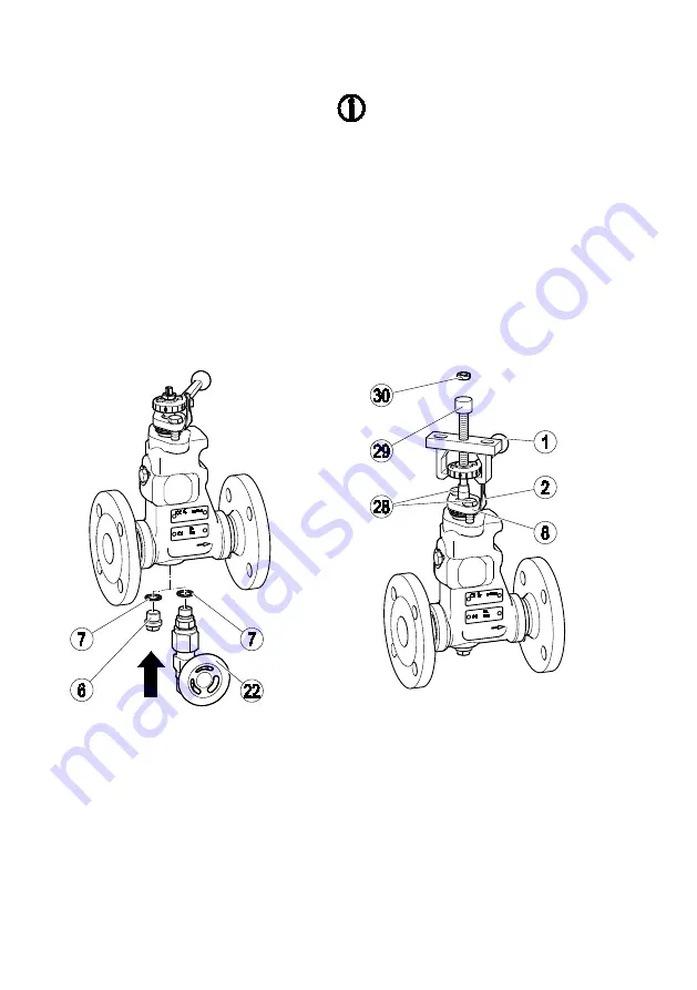
Remove the sealing plug (6).
Remove the sealing ring (7) from the body.
Insert the supplied sealing ring
A17 × 23 × 1.5 mm (7) in the hole.
Read and follow the instructions in the sampling
valve installation & operating manual.
Coat the thread and contact surfaces with
temperature-resistant lubricant.
The lubricant must have the same properties as
OKS 217.
Screw the sampling valve (22) into the hole in
the body with a torque of 130 Nm.
Positioning the control lever
In BA models, you can change the position
of the control lever by 180°.
You will find information on the required
tools on page 26.
Proceed as follows:
Remove the hex nuts (30) from the control lever.
Insert the puller (29) beneath the control lever.
Remove the control lever (1).
Remove the two stuffing box screws (28).
Remove the stuffing box gland (8).
Remove the dial (2).
Содержание BA 46
Страница 1: ...Continuous blowdown valve BA 46 BA 47 BAE 46 BAE 47 Original Installation Instructions 818609 04 ...
Страница 3: ...Dimensions and weights 39 Pressure temperature ratings 43 Manufacturer s Declaration 45 ...
Страница 19: ...19 Flow diagram for DN 15 to DN 32 capacity range up to 310 kg h ...
Страница 20: ...20 Flow diagram for DN 15 to DN 32 capacity range up to 1 020 kg h ...
Страница 21: ...21 Flow diagram for DN 15 to DN 32 capacity range up to 2 120 kg h ...
Страница 22: ...22 Flow diagram for DN 40 and DN 50 capacity range up to 1 340 kg h ...
Страница 23: ...23 Flow diagram for DN 40 and DN 50 capacity range up to 4 500 kg h ...
Страница 24: ...24 Flow diagram for DN 40 and DN 50 capacity range up to 6 300 kg h ...
Страница 39: ...39 Technical data Dimensions and weights BA BAE ...
Страница 46: ...46 ...
Страница 47: ...47 ...


