background image

Gerber P2C™ 1600 Cutters  

User’s Manual


General Information 

1-23


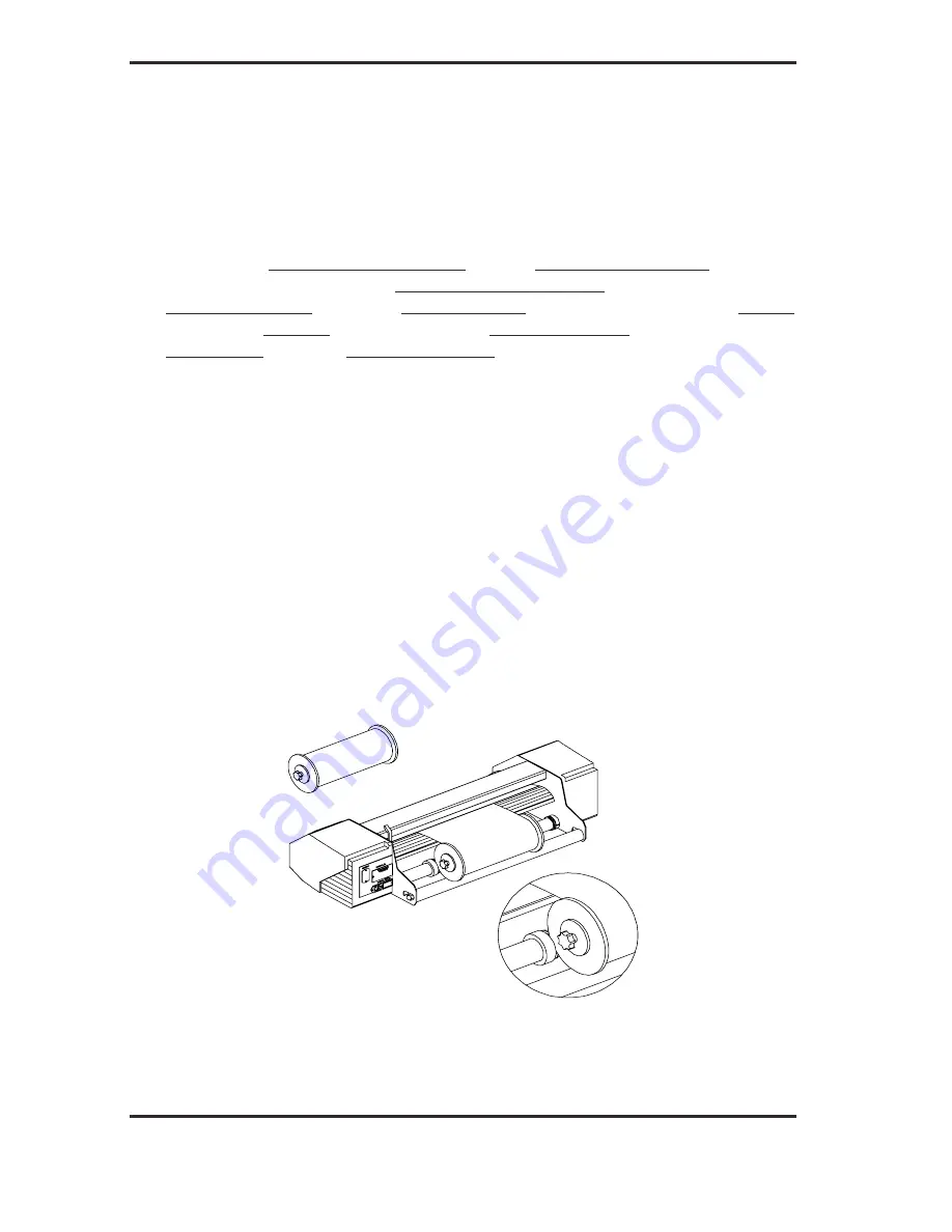
pressed  against  the  roll.  Place  the  flanges  on  the media support rollers at 
the rear of the cutter.  

 
3.  Position the flanges on the support rollers at the rear of the cutter.    
 

Slide the two media guides under the media roll so that each flange rests 
in  the  groove  in  the  guide.  In  this  position,  the  media  roll  and  guides  can 
be shifted left and right.  


Feed the media from the rear of the cutter.  


Position  the  left  edge  of  the  media  on  the  leftmost  drive sleeve and then 
check  to  see  whether  the  right  edge  of  the  media  is  positioned  over  the 
wide drive sleeve. If it is, the left pinch roller can be positioned in the detent 
above  the  leftmost  sleeve.  Then,  the  right  pinch  roller  can  be  positioned 
somewhere over the wide drive sleeve according to the media width. The 
right pinch roller can be located anywhere between the two outer detent 
positions  above  the  long  drive  sleeve.  This  flexibility  allows  a  variety  of 
media widths to be accommodated.  


Should the above procedure fail to work because the media is too narrow 
to reach the long drive sleeve, try positioning the left media edge over the 
second  drive  sleeve  in  from  the  left.  Then  position  the  right  media  edge 
somewhere on the wide drive sleeve. Repeat this process if the media is still 
found  to  be  too  narrow  by  locating  the  left  media  edge  over  the  third 
drive  sleeve  in  from  the  left.  Adjust  the  right  edge  of  the  media  as 
described above.  


Follow  the  same  general  procedure  when  loading  media  on  the  wider 
models  of  the  Gerber  P2C  cutters,  which  have  been  provided  with 
additional sleeves. 


If  necessary,  continue  to  reposition  the  media  until  both  edges  are 
positioned over a drive sleeve.  


FIGURE 1-9: 

FEEDING ROLL MEDIA USING MEDIA FLANGES


Содержание P2C 1600

Страница 1: ...e complete the attached Warranty Registration Card and return it to Gerber today or go through the online registration at http www gspinc products registration index html Failure to register may resul...

Страница 2: ...commercial environment This equipment generates uses and can radiate radio frequency energy and if not installed and used in accordance with the instruction manual may cause harmful interference to r...

Страница 3: ...on contained in this User Manual at any time without prior notice Unauthorized copying modification distribution or display is prohibited All rights reserved All queries comments or suggestions concer...

Страница 4: ...83 Gerber Road South Windsor CT 06074 USA 860 643 1515 Customer Service 800 222 7446 Technical Support 800 828 5406 860 644 6971 Fax 800 227 6228 860 871 3862 www gspinc com Copyright 2005 Gerber Sci...

Страница 5: ...cotchcal Scotchlite Controltac Comply and Panaflex are trademarks of the 3M Corporation DM PL and Houston Instrument are trademarks of Summagraphics Corporation HP GL is a trademark of Hewlett Packard...

Страница 6: ......

Страница 7: ...7 1 2 6 PERFORMANCE 1 7 1 2 7 CERTIFICATIONS 1 7 1 2 8 ENVIRONMENTAL 1 8 1 2 9 ELECTRICAL 1 8 1 3 CUTTER ACCESSORIES AND CONSUMABLES 1 9 1 4 REAR PANEL COMPONENTS 1 10 1 5 FRONT PANEL CONTROLS 1 12 1...

Страница 8: ...OCAL OPERATION 2 7 2 3 THE USER CONFIG MENU 2 8 2 3 1 KNIFE PRESSURE 2 10 2 3 2 KNIFE OFFSET 2 10 2 3 3 POUNCING PRESSURE 2 10 2 3 4 VELOCITY 2 10 2 3 5 OVERCUT 2 11 2 3 6 POUNCING GAP 2 11 2 3 7 SYST...

Страница 9: ...19 2 5 5 CAL MEDIA 2 20 2 5 6 CALIBRATION OPOS 2 20 2 5 7 OPOS SETTINGS 2 20 2 5 8 SYSTEM TESTS 2 20 2 6 SYSTEM TESTS 2 21 2 6 1 LANGUAGE 2 21 2 6 2 ROM REVISION 2 21 2 6 3 SERVICE PLOT 2 21 2 6 4 OPT...

Страница 10: ...ION 4 3 1 4 INTERFACE 4 1 4 1 INTRODUCTION 4 1 4 2 RS232 INTERFACE NOTES 4 1 4 2 1 SYSTEM SETUP 4 1 4 2 2 SERIAL INTERFACE CONNECTOR ON THE CUTTER 4 2 4 2 3 AVAILABLE SERIAL SIGNALS 4 2 4 3 USB INTERF...

Страница 11: ...C 1600 CONTROL PANEL 2 1 GERBER P2C 1600 CONFIGURATION SUBMENUS 2 4 FLOWCHART SHOWING FACTORY PRESET MENU SETTINGS 2 9 INTERNAL TESTS SUBMENUS 2 18 CLEANING OF THE DRIVE SLEEVES 3 2 LOCATION OF THE SE...

Страница 12: ......

Страница 13: ...enerated graphic designs on cut sheet or roll vinyl media By replacing the knife with a fiber tip pen these cutters can also be used to produce inexpensive previews of new graphic designs on paper Thi...

Страница 14: ...units User addressable resolution 0 1 mm 0 025 mm 0 001 or 0 005 Menu mode for selecting the cutter s power up operating configuration Convenient 2 line 16 character liquid crystal display LCD Extensi...

Страница 15: ...iption of the main components of the Gerber P2C 1600 cutters Step by step instructions for knife and pen installation and media loading Instructions for online and local mode operations Instructions f...

Страница 16: ...Sensor on Sensor off 42 30 1 7 1 2 Tracking Performance 0 1mm up to 12 m vinyl 760mm 0 004 up to 39 feet vinyl 30 0 1mm up to 4 m vinyl 760mm 0 004 up to 13 feet vinyl 30 Media Thickness 0 05mm to 0 2...

Страница 17: ...n using duly certified media operation in accordance with the functional specifications of the model is warranted Gerber should certify other media before use to ensure performance in compliance with...

Страница 18: ...contact your local dealer quoting the part numbers listed in table 1 9 The Gerber P2C cutters will only perform according to specifications if a genuine Gerber knife pen or pouncing tool is installed...

Страница 19: ...ot greater than 0 25 mm 0 010 Axial speed 50 to 1000 mm s 2 to 40 ips Default speed 800 mm s 32 ips Acceleration 3 G 3 G Addressable resolution 0 025 mm 0 1 mm 0 001 0 005 Default resolution 0 025 mm...

Страница 20: ...essential prerequisite to obtaining high cut quality Additionally media expansion or contraction may occur as a result of temperature variations To improve the dimensional stability of media allow it...

Страница 21: ...models OPTIONS ACCESSORIES CONSUMABLES Cutter Stand User s Manual Power Supply Cables Serial Interface Kit consisting of 9 pin to 9 pin cable 9 pin to 8 pin DIN Converter USB Cable Standard knife Sta...

Страница 22: ...P2C 1600 cutter read the following descriptions of the rear panel components Figure 1 1 shows the location of the main components 2 1 3 4 5 6 7 8 1 2 3 4 5 FIGURE 1 1 GERBER P2C 1600 REAR VIEW FOR PR...

Страница 23: ...es data will be the active interface until the cutter is reset 4 Power ON OFF switch This rocker switch turns the cutter on and off To switch the power ON press the I side of the rocker switch To swit...

Страница 24: ...FRONT VIEW 1 Pinch roller lever This lever is used to raise and lower the pinch rollers during media loading media loading is discussed in Section 1 8 2 Media Drive Sleeves The media drive sleeves mo...

Страница 25: ...ers The pinch rollers one at each side exert downward force through the media and onto the media sleeves This squeezing between the pinch rollers and media sleeves is what allows the cutter to accurat...

Страница 26: ...the earthed type The earth conductors serving said wall sockets must be properly connected to earth CAUTION Before plugging in the cutter s power cord to a power source make sure the cutter is set to...

Страница 27: ...erator to the risk of electric shock and will also lead to malfunctioning of the cutter 1 6 2 POWER UP PROCEDURE To power up the cutter proceed as follows 1 Be sure the cutter is securely attached to...

Страница 28: ...n in Figure 1 4 adjustment knob FIGURE 1 4 BLADE INSERTION 2 Set the knife blade length to zero by aligning the blade tip with the tip of the holder An easy way of performing this is by holding the kn...

Страница 29: ...ease the cutting depth Turning the screw counterclockwise will decrease the cutting depth FIGURE 1 6 SETTING KNIFE DEPTH 5 To install the knife into the tool carriage Loosen the clamp screw 2 and plac...

Страница 30: ...7 KNIFE DEPTH TEST PATTERN The knife depth is set correctly when the test pattern is visible on the front side of the media backing but not on the back In general you should increase the knife depth a...

Страница 31: ...d to be adjusted To prevent damage to the cutter check the depth of the blade tip and the quality of the cut whenever loading a different type of vinyl into the cutter 1 7 2 PEN INSTALLATION The Gerbe...

Страница 32: ...tall the pouncing tool proceed as follows 1 Loosen the clamp screw and swing the clamp arm back Remove the knife holder or pen refer to Fig 1 6 2 Install the pouncing tool close the clamp arm and tigh...

Страница 33: ...utter next to the control panel The rollers must be raised before media can be loaded into the cutter When raised the pinch rollers can be moved manually left and right along the pinch roller shaft Th...

Страница 34: ...d on the head guide The center low pressure roller is used to enhance media routing and keep the vinyl flat Ideally this roller should be positioned halfway between the two edge rollers but always ove...

Страница 35: ...drive sleeve according to the media width The right pinch roller can be located anywhere between the two outer detent positions above the long drive sleeve This flexibility allows a variety of media...

Страница 36: ...by sliding the media guides left and right as needed along the media support rollers 5 The pinch rollers should be positioned over the drive sleeves and about 3 to 15 mm 0 1 to 0 6 in from the edges...

Страница 37: ...ll the media manually from the roll The cutter will unroll the media automatically during the load sequence 7 The positioning and routing of sheet material is identical to that of roll media 8 The cut...

Страница 38: ...e consisting of A media width measurement A 45 test A length of media is unwound equal to the width measured between the pinch rollers When the cutter indicates that it is ONLINE it is ready to receiv...

Страница 39: ...the knife i e the origin can be repositioned to any location Press the key to confirm the selected point of origin The media length needed for a task can be entered by pressing the and jogging keys T...

Страница 40: ...track on the vinyl 80099 01 99 4 The cutter is now ready to receive a file 80099 01 99 4 The cutter has been selected by the computer When the built in media sensors detect the end of the roll the me...

Страница 41: ...2 OPERATION 2 1 THE CONTROL PANEL Figure 2 1 shows the control panel of the Gerber P2C 1600 cutters The main functions of the liquid crystal display LCD and the control panel keys are explained in the...

Страница 42: ...OAD KEY The key RESET LOAD is used to move the origin initiate a load sequence reset the cutter abort the cut in progress or recut the last file When the key RESET LOAD is pressed the cutter goes offl...

Страница 43: ...fline will return the cutter to online status and the suspended operation will resume While the cutter is offline the following operations can be performed Press the or jogging key to move the tool ca...

Страница 44: ...selected by the host computer for a cutting or plotting operation or deselected by the host computer Pressing the or key will cause the cutter to go offline in order to initiate another operation The...

Страница 45: ...em 2 1 8 THE TOOL UP DOWN KEY The key TOOL UP DOWN is used while the cutter is offline to raise or lower the tool Pressing the key once will lower the tool onto the media Pressing the key again will r...

Страница 46: ...iguration In all other cases the cutter is offline When online the cutter can be addressed by the host computer which means that the cutter will execute cutting or plotting instructions issued by the...

Страница 47: ...ing any of these keys will suspend the current cutting plotting operation until the cutter is again put online 2 2 2 LOCAL OPERATION Local operation is only possible while the cutter is offline Local...

Страница 48: ...ER CONFIG 1 4 is displayed 3 Press the or jogging key until the desired configuration number is displayed next to USER CONFIG NOTE Before altering any of the items in the USER CONFIG menu make sure th...

Страница 49: ...3 4 3A 80099 4 3A 80099 4 3A 80099 5 99 3 A 3 B 3 A 3 B 3 A 3 B 3 53 53 0 7B 4 7 B 3C C 4 7 B 453 7B 4 C 4 C3 3 3 4 7 5 B 7 5 B 3 B 3 5 3 4 57 577 0 99 54 4 57 D5 7 53 EF00 3 4 BB5 7 5 3 5 3A 4 57 6 B...

Страница 50: ...e fine tuning may be necessary because of the knife s mechanical tolerances To verify the knife offset a test can be cut by pressing the 1 key If the offset value is set too low the rectangles will no...

Страница 51: ...ING GAP The pouncing gap submenu is used to set or modify the distance between the pounced holes Pouncing gap only applies when the machine is in pounce mode The default pouncing gap is 1 mm The value...

Страница 52: ...uage The Gerber P2C 1600 cutters support DM PL HP GL and HP GL 2 The active plotting language is marked with an asterisk on the LCD NOTE The cutter s active cutting plotting language MUST match the ac...

Страница 53: ...nu units is marked with an asterisk on the LCD 2 4 6 ADDRESSING The ADDRESSING submenu is used to select the cutter s default DM PL user addressable resolution The user addressable resolution can be s...

Страница 54: ...T 8 1 8 data bits no parity bit 8 high 1 EVEN 7 data bits 1 parity bit parity bit even ODD 7 data bits 1 parity bit parity bit odd The active parity setting is marked with an asterisk on the LCD NOTE...

Страница 55: ...will only be displayed if PLOT LANGUAGE is set to HP GL See Paragraph 2 4 3 The HP GL ERRORS submenu can be set to REPORTED or IGNORED The feature is activated by selecting REPORTED and is normally us...

Страница 56: ...ect commands the P and SP commands respectively are ignored or accepted When the TOOL COMMAND option is set to ACCEPT the P or SP commands will change the selected tool in the cutter according to the...

Страница 57: ...essure Pressing the 1 key will activate the configuration menu which allows you to set the cutting pressure and cut length 1 CUT LENGTH This parameter determines the length that will be cut with full...

Страница 58: ...s displayed 6 To perform the plot press the key To exit this menu and go to another menu press the key until the desired menu is displayed Press the key to exit all menus and return the cutter to onli...

Страница 59: ...is altered The resulting plot should be kept with the cutter documentation in order to provide other users with details about the unit s actual configurations 2 5 3 CONFIDENCE CUT The CONFIDENCE cut p...

Страница 60: ...brate the Optical Positioning System OPOS This calibration is normally done at the factory When the system is no longer working precisely a calibration test must be performed Calibration determines an...

Страница 61: ...ing The information on the LCD can be displayed in English French German Spanish Italian or Dutch 2 6 2 ROM REVISION Press the key to view information about the cutter s ROM revision This information...

Страница 62: ...asurement indicates 105 mm then 105 mm can be entered for that particular line by which the system will be calibrated 2 6 7 RS232 TEST The RS232 TEST verifies the cutter s RS 232 C serial communicatio...

Страница 63: ...ate the knife and pen pressures and to set the knife and pen landings After calibration the values are saved in the system s non volatile RAM A tension gauge of 100 gr and 500 gr is required to execut...

Страница 64: ......

Страница 65: ...traction as the media will tend to slip between the pinch rollers and the drive sleeves To clean the drive sleeves proceed as follows 1 First disable the sensors through the cutter s control panel or...

Страница 66: ...me dirty with accumulated residue from the media that may cause the cutter to malfunction To clean the sensor area proceed as follows 1 The sensors are located on the right side of the cutter one on t...

Страница 67: ...lied to your site you must change the voltage BEFORE powering on the cutter When changing the voltage setting you will also have to change the fuses as appropriate for the voltage To change the fuse s...

Страница 68: ......

Страница 69: ...rst will stay active and the others will be deactivated The deactivated ports can only be reactivated by restarting the cutter Connecting more than one of the three communication cables to the cutter...

Страница 70: ...re making your own cable only a few of the cutter s pins will actually need to be connected to the host computer To ensure optimal results the cable length should not exceed 4 8 m 16 feet It should be...

Страница 71: ...t a USB driver The computer should be using either the WIN98 or WIN2000 operating system 2 Plug the cable connector securely into the cutter s USB interface connector Plug the other end of the cable i...

Страница 72: ...ly install the driver and the Gerber PortMapper utility Restart the computer once installation is complete Next to the cutter s USB connector is a small light emitting diode LED that will either be on...

Страница 73: ...Ground 4 Data 3 22 Ground 5 Data 4 23 Ground Pin n Definition Pin n Definition 6 Data 5 24 Ground 7 Data 6 25 Ground 8 Data 7 26 Ground 9 Data 8 27 Ground 10 Acknowledge 28 Ground 11 Busy 29 Ground 1...

Страница 74: ......

Страница 75: ...s been evaluated and extensively tested on the Gerber P2C 1600 cutters Only duly certified media should be used to ensure operation in compliance with the functional specifications of the Gerber P2C c...

Страница 76: ...R SCIENTIFIC PRODUCTS CONTACT INFORMATION Gerber Scientific Products 83 Gerber Road South Windsor CT 06074 USA 860 643 1515 Customer Service 800 222 7446 Technical Support 800 828 5406 860 644 6971 Fa...

Отзывы: