background image


Page 45 


术语表


用于描述裁割桌上移动和位置的假象线。裁床使用三条轴线:


C (

刀片方


), X (

与桌长平行

Y (

与桌宽平行

)

。见


C-

, X-

Y-

轴。


横梁


携带并支撑裁头沿着桌面的长度和宽度方向移动。


横梁控制面板


(BCP)


连接在裁床上控制刀头和横梁一组控制器。


C-


刀片裁割的假想直线。


裁割文件


计算机数据文件提示

GERBERcutter 

如何从铺开的面料上裁割样片。


(见

排版图

.


默认


工厂

编入的设置。在监督员选择其它设置覆盖默认设置之前,

系统一直使

用默

认设置。


空走


刀片在材料上端移动的距离。


空运转


检验裁床在排版图上裁割和钻孔功能,但是不插入刀片或裁割面料。


紧急停止

(E-Stop)


按入红色紧急停止开关或黄色紧急停止安全棒,立即停止裁床所有运
作。


Содержание DCS 1500

Страница 1: ...Started Getting Manual Manual de Inicio...

Страница 2: ......

Страница 3: ...DCS 1500 DCS 2500 GERBERcutter Getting Started Manual...

Страница 4: ......

Страница 5: ...hall be used in the manufacture or reproduction of the articles shown and the delivery shall not constitute any right or license to do so The information in this document is subject to change without...

Страница 6: ...Page iv English Revision History Date Revision Author Changes 09 2008 B N A Original 02 2018 C SB Rebranded entre document Reformatted English and Chinese Replaced Spanish translation...

Страница 7: ...MAINTENANCE ALONE 6 ENERGIZED CIRCUITS 6 DE ENERGIZE CUTTER BEFORE MAINTENANCE AND INACTIVITY 7 COMPRESSED AIR 7 DO NOT OPERATE IN AN EXPLOSIVE ATMOSPHERE 7 MOVING MACHINERY 7 REPLACING PARTS 7 LASER...

Страница 8: ...LE 22 10 VACUUM VALVES DCS 2500 ONLY 23 11 VACUUM STARTER BOX VACUUM ON OFF 24 CUTTING TOOLS 25 TOOL HOLDERS 26 CUTTING TOOL INSTALLATION 27 KNIFE CUTTER CALIBRATION PROCEDURE 28 OPERATING THE DCS 150...

Страница 9: ...up to three tools and a pen for plotting and annotation Pneumatic system permits adjustment of pen and cutter downforce Split table operation for different applications on either side of table Self co...

Страница 10: ...Centers Gerber s worldwide Customer Solution Centers are staffed by multi lingual trained experts at all hours To find a local Customer Solution Center visit www gerbertechnology com Advanced Technol...

Страница 11: ...prevent personal injury death or equipment damage Safety Labels These safety labels are located at various parts of the equipment including the cutter head beam and electrical components Symbol Descri...

Страница 12: ...Electrical shock potential Friction hazard Moving member Pinch point Hand crush force from above Danger Moving parts can crush and cut Warning To avoid injury read and understand the getting started...

Страница 13: ...cede some steps or procedures Always follow these precautions to prevent personal injury or equipment damage Warnings are put before procedures that could result in personal injury death or equipment...

Страница 14: ...rate the cutter in any manner other than for the purpose that it was designed and sold without prior consultation with Gerber Technology Equipment Training Operate this machine only after approved tra...

Страница 15: ...g flammable liquids such as cleaning solvents Do not operate the cutter near flammable gases or fumes Moving Machinery Keep hands away from all moving machine parts to prevent personal injury Make sur...

Страница 16: ...l injury Cutting Tools Use only Gerber supplied cutting tools Be sure all tools are correctly installed on the equipment and properly mapped in the CutWorks software Failure to do so may result in equ...

Страница 17: ...tion in two modes Local and Online Local mode allows the operator to manually control hardware functions such as moving the cutter head and beam Jogging mode is accessed through local mode and allows...

Страница 18: ...glish Figure 3 GERBERcutter overview ID Component E Stop switch E Stop bumper arm Beam control panel BCP Control desk typical location not supplied by Gerber with control box Cutter head Beam Festoon...

Страница 19: ...ox The E Stop function should be used when there is danger to people the cutter or the cut material This function is activated when Any of the two red E Stop switches are pushed Any of the four yellow...

Страница 20: ...Page 12 English Figure 4 E Stop switch Figure 5 E Stop bumper arms and switch festoon side ID Component E Stop bumper arm E Stop switch...

Страница 21: ...the Reset button on the control box status board see Figure 6 To recover a cut file that was functioning before the E Stop 1 On the Toolpath menu select Clear Halt Marker 2 On the Machine menu select...

Страница 22: ...Page 14 English Figure 6 Beam control panel ID Component E Stop bumper arm Keypad E Stop switch Joystick...

Страница 23: ...cified calibrations and digitizing mode Display Screen Displays the system mode and details of specified calibrations Up Arrow key Navigates menus and is used in specified calibrations Plus key Used i...

Страница 24: ...once or twice to return to online mode From online mode to local mode 1 Press the Up Arrow key or Down Arrow key on the beam control panel keypad 2 Local mode appears on the display screen on the bea...

Страница 25: ...eck the display screen to verify the system is in local mode 4 Press the Enter key 5 To move the cutter head and beam Move the joystick in the desired direction 4 Control Desk The control desk is typi...

Страница 26: ...sure regulator Knob that controls the air pressure to the corresponding tool holders Status board Provides information about the cutter s operating status System energized light Illuminates when hardw...

Страница 27: ...An illuminated red light indicates a fault in a specific axis System online An illuminated green light indicates when servo motors are energized Control power Green light that indicates if the Main P...

Страница 28: ...et button when prompted on the computer 4 Log on to the computer with username and password when prompted Turn off Cutter Note The computer must be turned off separately 5 Push the control box AC Powe...

Страница 29: ...English Figure 10 Cutter head and beam ID Component Head Beam 7 Festoon Side Cover The festoon side cover is on the festoon side of the beam It is equipped with one E Stop switch and two E Stop bumpe...

Страница 30: ...E Stop bumper arm E Stop switch 8 Table Surface and 9 Vacuum under table The table surface is made of plastic surface panels on top of an aluminum surface The plastic surface is porous to allow vacuum...

Страница 31: ...ary based upon table length Be sure that the correct valves are opened and or closed before cutting The vacuum valves have the following labels with corresponding arrows O open C closed Turn the vacuu...

Страница 32: ...cuum valve OFF position 11 Vacuum Starter Box Vacuum On Off The vacuum starter box is mounted on the cutter The vacuum operates independently from the cutter table and computer It has three buttons Va...

Страница 33: ...system Push the blue 3 Reset button to reset the vacuum system Cutting Tools The cutting tools listed below are available for use with the DCS 1500 2500 cutters The wheel tool knife cutter pen and la...

Страница 34: ...r V notch V Notch Tool Stamping the desired notch shape V Punch Tool Making small diameter holes in fabric Can be programmed to spin or make several hits to penetrate materials Pen Pen Tool Used for c...

Страница 35: ...with a 5 64 in hex wrench The calibration procedure for the Knife Cutter is explained in the Knife Cutter Calibration Procedure section Each cutting tool is equipped with a set screw that can be loose...

Страница 36: ...ting tool to the tool holder Knife Cutter Calibration Procedure The Knife Cutter must be calibrated for the material thickness each time a new material is cut This procedure requires a 5 64 in hex wre...

Страница 37: ...h flat surface 3 Put the caliper edge on top of depth gauge 4 Use the caliper to measure the material thickness at the thickest part of the material 5 Make note of the caliper measurement 6 Place the...

Страница 38: ...Locking setscrew Depth limiter Adjusting setscrew 7 Slightly loosen the locking setscrew and turn the adjusting setscrew so the blade is slightly protruding out of the depth limiter 8 Place the entir...

Страница 39: ...s to the material thickness noted in step 4 10 Turn the adjusting setscrew until the depth gauge face plate dial reads 0 010 to 0 015 more than the material thickness noted in step 4 11 Tighten the lo...

Страница 40: ...ting Consideration must be given to the material being cut and some common practices that are intuitive in manual cutting are not necessarily intuitive to an automated cutting system Unlike hand cutti...

Страница 41: ...ows the cutter and negatively affects curve smoothness The DCS 1500 2500 can support multiple drill punch sizes from 1 10 mm 1 32 to 1 2 in AccuMark and CutWorks toolpaths can be configured to cut hol...

Страница 42: ...complete this cut use 18 in x 18 in 45 7 cm x 45 7 cm of fabric or paper Read the Safety Instructions section before operating the cutter Note Before proceeding check the cutter head and confirm that...

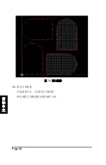
Страница 43: ...click Open b Navigate to C ProgramFiles CutWorks Samples GT TEMPLATE nc c Click Open The NC Import Options box General tab opens see Figure 18 7 Enter the following properties as shown In the Text Hei...

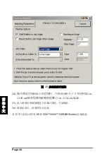
Страница 44: ...Import the GT TEMPLATE nc file Click the M19 Notch tab on the NC Import Options box 9 Enter the following properties as shown Under Type click AccuMark Lectra Under Length select Max length to convert...

Страница 45: ...Figure 21 NC Import Options box M19 Notch tab Note Notches are represented by notch entities on the perimeter of each piece see Figure 20 These notch entities can be converted to v notches as describe...

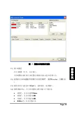
Страница 46: ...Page 38 English Figure 22 Notch entities 10 Map layers to tools On the Machine menu click Map Layers to Tools The Map Layers to Tools box opens...

Страница 47: ...12 If necessary right click the currently selected Notch line tool and select Notcher 13 If necessary right click on the currently selected Cut line and select Wheel Cutter 14 Enter the following prop...

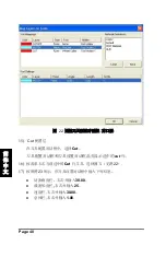
Страница 48: ...ool Settings box 16 If necessary right click the currently selected cut line tool and select Wheel Cutter as shown in Figure 23 17 Enter the following properties in the Tool Settings box as shown in F...

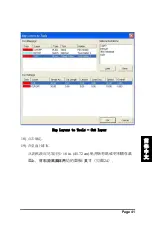
Страница 49: ...Figure 25 Map Layers to Tools Cut layer 18 Click OK 19 Spread material on table Spread paper or fabric on the table at least 18 in 45 72 cm from the ends of the cutter and 1 inch from each of the cut...

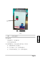
Страница 50: ...ng material on table ID Component Distance of 18 inches or more Distance of 1 inch or more 20 Open vacuum valves Turn all vacuum valves to the Open position 21 Energize the vacuum Push the green ON bu...

Страница 51: ...e On the Machine menu click Cut Job The Starting Options box opens 23 Enter the following properties in the Starting Options box as shown in Figure 26 a Select Shift Entities to Job Origin b In the Jo...

Страница 52: ...laser light or pen 1 in 2 54 cm up and 1 in 2 54 cm over the lower left corner of the material 25 Push the Enter button on the beam control panel keypad to begin cutting 26 Remove the material from t...

Страница 53: ...er head and beam C Axis An imaginary straight vertical line that the knife rotates around Cut file A computer data file that tells the GERBERcutter how to cut patterns or markers from a spread of mate...

Страница 54: ...beam in local mode Laser light A tool that is attached to the cutter head and is used as a pointer Local mode This mode allows the operator to manually control hardware functions such as moving the cu...

Страница 55: ...e take off end on the keypad side Parameter A software setting defined in a marker setup file Pause This function stops cut processing after the current cut segment is complete It is activated by push...

Страница 56: ...ol holder The machine mechanism that holds tools For example the tool holder for the pen is the pen holder X Axis Imaginary horizontal line parallel to table length from take on end to take off end Y...

Страница 57: ...for different applications Pneumatic vacuum shut off blast gate Used to shut off vacuum to entire or half of table if vacuum zones are configured Reverse Air Blower used to float non porous materials...

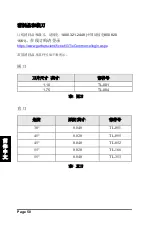
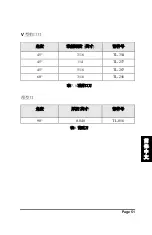
Страница 58: ...part numbers follow Wheel Cutter Blades Blade size inches Part number 1 10 TL 001 1 75 TL 004 Figure 30 Wheel cutter blades Knife Cutters Angle Thickness inches Part number 30 0 040 TL 051 45 0 020 T...

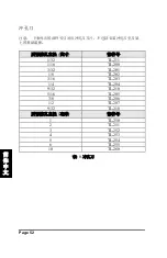
Страница 59: ...y do not include the base assembly which is required to mount punches to the tool holder Desired hole diameter inches Part number 1 32 TL 211 1 16 TL 200 3 32 TL 201 1 8 TL 202 3 16 TL 203 1 4 TL 204...

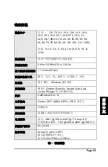
Страница 60: ...lade knife cutter pen chisel tool wheel v notch punch Computer PC based Windows OS Front End Systems Compatible with Gerber ScanVec Assyst Auto Cad Lectra Polygon most software packages Software CutWo...

Страница 61: ...DCS 1500 DCS 2500 GERBERcutter Manual de inicio...

Страница 62: ......

Страница 63: ...utilizar este documento ni sus contenidos en la redacci n o reproducci n de los art culos mostrados y su suministro no supondr la concesi n de derechos o licencias para hacerlo La informaci n en este...

Страница 64: ...Page iv Espa ol...

Страница 65: ...ACI N OPERATIVA DE EQUIPOS 6 MANTENIMIENTO EN SOLITARIO 6 CIRCUITOS ENERGIZADOS 6 AIRE COMPRIMIDO 6 NO UTILICE LA M QUINA EN UNA ATM SFERA EXPLOSIVA 6 MAQUINARIA EN MOVIMIENTO 7 SUSTITUCI N DE PIEZAS...

Страница 66: ...DO APAGADO DEL VAC O 23 HERRAMIENTAS PARA DCS 1500 2500 24 DCS 1500 2500 PORTA HERRAMIENTAS 26 COLOCAR LAS HERRAMIENTAS DE CORTE 26 PROCESO DE CALIBRACI N DE LA CUCHILLA TANGENCIAL 27 OPERATIVA DEL CO...

Страница 67: ...operativos Windows Capacidad de montar hasta tres herramientas m s un bol grafo para trazado y anotaci n Ajuste de la presi n neum tica de las herramientas Divisi n de la mesa de trabajo para permiti...

Страница 68: ...cliente de Gerber de todo el mundo ponen a su disposici n en todo momento expertos multiling es con gran formaci n Para encontrar un centro local de atenci n al cliente visite http www gerbertechnolog...

Страница 69: ...dad Read and understand all safety instructions before operating the equipment to prevent personal injury death or equipment damage S mbolo Descripci n Toma el ctrica de chasis a tierra Toma de tierra...

Страница 70: ...a tierra Toma de tierra Advertencia Objeto punzante Peligro Partes m viles pueden cortar y da ar Advertencia Lea y entienda el manual de usuario antes de utilizar esta m quina Advertencia Para evitar...

Страница 71: ...s y precauciones preceden a algunos pasos o procedimientos Siga siempre estas precauciones para prevenir lesiones personales o da os en el equipo Las advertencias se anteponen a procedimientos que pod...

Страница 72: ...e proceder a mantenimientos en las partes con presencia de voltajes el ctricos Debe haber un interruptor principal para quitar la alimentaci n el ctrica compatible con la normativa de la red el ctrica...

Страница 73: ...e Clase IIIr con una potencia de pico de 5 mW a una longitud de onda de 670 nm Un uso de controles ajustes o ejecuci n de procedimientos no incluidos en este manual pueden resultar en una exposici n p...

Страница 74: ...mercializados a partir del 13 de agosto de 2005 La directiva RAEE exige la recogida y el tratamiento de equipos el ctricos y electr nicos al final de su vida til Consulte los requisitos regionales esp...

Страница 75: ...ero l ser Se accede al modo de Moviendo con palanca jogging a trav s del modo local y permite al operador mover el cabezal de corte y el puente El modo en l nea es el modo predeterminado cuando la cor...

Страница 76: ...nterruptores de parada de emergencia E Stop en adelante 2 Paros de emergencia lateral Dos interruptores E Stop rojos ver Figura 3 y cuatro interruptores E Stop amarillos Los paros laterales vea la Fig...

Страница 77: ...ientas y elimina todas las fuentes de alimentaci n del servo deteniendo todo movimiento S lo el ordenador se mantiene con alimentaci n despu s de una parada de emergencia Los datos se guardar n y debe...

Страница 78: ...de una parada de emergencia 1 Si sigue presionado alg n interruptor de emergencia g relo y su ltelo Vaya al paso 3 2 Si se ha empujado un paro lateral vuelva a centrarlo y vaya al paso 3 3 Pulse el b...

Страница 79: ...eleccione Reiniciar trabajo abortado 3 Pulse la tecla Intro en el teclado del panel de control del puente Panel de control del puente El panel de control del puente se ubica en el lado keypad del puen...

Страница 80: ...Page 14 Espa ol ID Component Teclado keypad vea Figura 6 Paro de emergencia seta Joystick Teclado Keypad Figure 6 Teclado del panel de control del puente...

Страница 81: ...so de corte o reanuda tras una pausa Se utiliza tambi n para confirmar la ejecuci n de otros comandos Tecla Utilizada en calibraciones Flecha Abajo Permite navegar por las opciones del men NOTA La m q...

Страница 82: ...n en el teclado del panel de control del haz 3c Joystick El Joystick permite al operador mover el cabezal de corte y el puente Para usar el Joystick 1 Compruebe la pantalla de visualizaci n en el pan...

Страница 83: ...liza para regular la presi n del portador de herramienta 3 del bol grafo y de subida de las herramientas Reguladores de presi n Se utilizan para regular las presiones de los portadores de herramientas...

Страница 84: ...taci n el ctrica de motores y otros componentes 4b Panel de Estado Figure 8 Panel de estado ID Component ensores de Pos Inicio Luz verde indica que el sensor de posici n de inicio est activo Paros de...

Страница 85: ...cortadora y la computadora se energizan por separado Activar M quina de corte NOTA La computadora debe estar funcionando antes de encender la cortadora 1 Coloque el interruptor de alimentaci n de CA d...

Страница 86: ...re de la superficie de la mesa y son controlados por CutWorks El cabezal cortador se mueve a lo largo del puente y el puente a lo largo de la mesa El cabezal cortador sostiene los portaherramientas un...

Страница 87: ...n La tapa del lado catenaria opuesto al operador est equipada con un paro de emergencia tipo seta y dos paros laterales amarillos de emergencia Figure 10 Tapa lado catenaria ID Component Tapa Paro lat...

Страница 88: ...al bajo la mesa 10 V lvulas de vac o DCS 2500 solamente Hay diversas v lvulas de vac o bajo la mesa en el lado operador Estas v lvulas controlan de vac o en la mesa Los lugares y la cantidad var an se...

Страница 89: ...re 12 V lvula cerrada 11 Caja de arranque de vac o Encendido apagado del vac o La caja de arranque por vac o se monta en la cortadora El vac o funciona independientemente de la mesa de corte y del ord...

Страница 90: ...mientas de corte que se enumeran a continuaci n est n disponibles para su uso con el cortador DCS 1500 2500 Herramienta tipo roldana cortador de cuchilla tangencial bol grafo y puntero luz l ser se in...

Страница 91: ...os de giro muy peque os Piquetero en raja ealiza un piquete recto en el material Piquetero en V Realiza un piequete en forma de V en el material Taladro Realiza un taladro en el material Bol grafo Bol...

Страница 92: ...entas de corte PRECAUCI N Desactive los servos antes de cambiar las herramientas de corte Cada herramienta de corte est equipada con un tornillo de ajuste y fijaci n Este tornillo precisa de una llave...

Страница 93: ...cial La profundidad de la cuchilla tangencial debe ser calibrada para el espesor del material cada vez que se utiliza Este procedimiento requiere la llave hexagonal de 5 64 el calibre de profundidad y...

Страница 94: ...bre el calibre de profundidad 3 Utilice el pie de rey para conocer el grosor del material a cortar 4 Anote la medida de profundidad del material 5 Coloque el limitador de profundidad marr n sobre el p...

Страница 95: ...n Limitador de profundidad Tornillo ajuste de profundidad 6 Afloje ligeramente el tornillo de fijaci n y gire el tornillo de ajuste para que la cuchilla sobresalga ligeramente del limitador de profun...

Страница 96: ...ndicado en el paso 4 9 Gire el tornillo de ajuste hasta que la placa frontal del calibrador de profundidad del dial marque de 0 010 a 0 015 aprox 0 2 a 0 3mm m s que el grosor del material 10 Apriete...

Страница 97: ...vac o Afilado de la cuchilla Control de los movimientos Preparaci n de datos La preparaci n de datos para una cortadora GERBERcutter es diferente a la preparaci n para corte manual Se debe tener en c...

Страница 98: ...igitalizar la piezas tenga en consideraci n estos puntos Siempre empiece a digitalizar una pieza o patr n por una esquina Evite empezar en medio de una curva Si el corte comienza en una curva la pieza...

Страница 99: ...zar la cuchilla Control de los movimientos El control de movimiento se refiere al movimiento de la herramienta de corte a trav s del material junto con la velocidad a la que los realiza Debe considera...

Страница 100: ...n en CutWorks Introduzca el nombre de usuario y la contrase a cuando se le solicite en el cuadro de inicio de sesi n 5 Inicializar el cortador ADVERTENCIA El puente del corte se mover ADVERTENCIA El...

Страница 101: ...ure 19 Opciones importaci n tipo NC Pesta a General 8 Importe el archivo GT TEMPLATE nc Haga clic en la pesta a M19 Notch en el cuadro NC Import Options Opciones de importaci n de NC v ase Figura 20 9...

Страница 102: ...n Colocaci n haga clic en Antes de las polil neas Figure 20 Pesta a M19 de opciones importar nc NOTA Los piquetes est n representados por entidades de piquete en el per metro de cada pieza ver Figura...

Страница 103: ...Espa ol Figure 21 Notch entities 10 Asignar capas a herramientas En el men M quina haga clic en Asignar capas a herramientas Se abrir el cuadro Map Layers to Tools Capas de mapa a herramientas ver Fi...

Страница 104: ...rat n en la herramienta y seleccione Notcher como se ilustra en la Figura 23 13 Si es necesario haga clic con el bot n derecho del rat n en la l nea de corte actualmente seleccionada y seleccione la c...

Страница 105: ...en el cuadro Asignaciones de herramientas y la opci n Cuadro Configuraci n de la herramienta 16 Si es necesario haga clic con el bot n derecho del rat n en la herramienta L nea de corte actualmente s...

Страница 106: ...eral haga clic con el bot n derecho del rat n y escriba 1 00 Figure 24 Asignar herramientas a capa de corte 18 Click OK 19 Extienda el material sobre la mesa de corte Extienda papel o tela sobre la me...

Страница 107: ...tor de vac o Pulse el bot n verde de la caja de arranque del motor o active el m todo que tengan para activar la succi n en la mesa 22 Corte el fichero seleccionado En el ordenador En el men m quina c...

Страница 108: ...de control del puente para mover el puntero l ser o bol grafo 1 pulg 2 54 cm hacia arriba y 1 pulg 2 54 cm m s de la esquina inferior izquierda del material 25 Pulse el bot n Enter en el teclado del...

Страница 109: ...erentes aplicaciones Pneumatic vacuum shut off blast gate Se usa para cerrar el vac o a la mesa entera o a la mitad de la mesa si se configuran las zonas de vac o Reverse Air Soplador de aire reverso...

Страница 110: ...meros de pieza correspondientes son que se enumeran a continuaci n Cuchillas circulares Di metro Referencia 1 10 TL 001 1 75 TL 004 Figure 28 Cuchillas circulares Cuchillas tangenciales ngulo Ataque...

Страница 111: ...nz n solamente No incluyen el conjunto de la base que se requiere para montar en el portaherramientas Di metro del taladro Pulgadas Referencia 1 32 TL 211 1 16 TL 200 3 32 TL 201 1 8 TL 202 3 16 TL 20...

Страница 112: ...genciales piqueteros en V piqueteros rectos y bol grafo Computador PC basados en Sistema operativos Windows Sistema de visualizaci n Compatible con Gerber ScanVec Assyst AutoCad Lectra Polygon y otros...

Страница 113: ...DCS 1500 DCS 2500 GERBERcutter...

Страница 114: ......

Страница 115: ...Page iii 2017 DCS1500 2500 GERBERcutter AccuMark CutWorks GERBERcutter MicroMark GerberTechnology LLC 24 Industrial Park Road West Tolland CT 06084 USA 860 871 8082...

Страница 116: ...Page iv...

Страница 117: ...Page v III III 1 1 1 2 2 2 2 2 3 3 3 5 5 5 6 6 6 6 6 6 6 7 7 7...

Страница 118: ...vi WEEE 7 9 9 10 11 1 E STOP 2 11 2A 13 3 BCP 13 3A 15 3B 16 3C 17 4 17 4a 17 4b 19 4c 20 5 6 21 7 22 8 9 22 10 DCS 2500 23 11 25 DCS 1500 2500 26 DCS 1500 2500 27 28 28 DCS 1500 2500 GERBERCUTTER 32...

Страница 119: ...Page vii 32 32 32 33 33 34 DCS 1500 2500 34 45 49 DCS 2500 49 50 50 50 V 51 51 52 53...

Страница 120: ......

Страница 121: ...Page 1 DCS1500 2500 GERBERcutter DCS 1500 2500 GERBERcutter Windows 3 1...

Страница 122: ...___________ ___________________________ DCS 1500 2500 GERBERcutter _ ___________________________ ___________________________ www gerbertechnology com default asp contentID 266 1 800 826 3243 1 860 871...

Страница 123: ...Page 3 84 8 984 7080 GERBERcutter GERBERcutter...

Страница 124: ...Page 4...

Страница 125: ...Page 5 2...

Страница 126: ...Page 6 A C...

Страница 127: ...Page 7 Class IIIr 5 mW 670 nm CutWorks WEEE 2005 8 13 2002 96 EC...

Страница 128: ...Page 8 1 WEEE...

Страница 129: ...Page 9 DCS 1500 2500 GERBERcutter DCS 1500 2500 AccuMark CutWorks Designer CutWorks DCS 1500 2500...

Страница 130: ...Page 10 1 BCP GERBER...

Страница 131: ...Page 11 DCS 2500 1 E Stop 2 2 2 3 2 4...

Страница 132: ...Page 12 2 3...

Страница 133: ...Page 13 2a 1 3 2 3 3 6 4 6 1 2 3 3 BCP BCP...

Страница 134: ...Page 14 4 5...

Страница 135: ...Page 15 3a 5 F1 F2 F3 F4...

Страница 136: ...Page 16 3b 1 2 1...

Страница 137: ...Page 17 1 2 a 3c 1 2 3 4 5 4 Gerber 4a...

Страница 138: ...Page 18 6 3 1 2 7 AC...

Страница 139: ...Page 19 4b 7 X Y T 24V...

Страница 140: ...Page 20 4c AC 1 AC 2 3 4 1 AC 2...

Страница 141: ...Page 21 5 6 CutWorks 8...

Страница 142: ...Page 22 7 9 8 9...

Страница 143: ...Page 23 10 DCS 2500 3 O C O 10 10 C 11...

Страница 144: ...Page 24 11...

Страница 145: ...Page 25 11 3 12 1 2 3...

Страница 146: ...Page 26 DCS 1500 2500 DCS 1500 2500 V V V V U...

Страница 147: ...Page 27 3 DCS 1500 2500 13...

Страница 148: ...Page 28 5 64 1 14 1 Cutting tool installation 2 3 5 64 5 64...

Страница 149: ...Page 29 1 2 0 Depth gauge with flat surface 3 4 5 16 6...

Страница 150: ...Page 30 16 7 17 8 4...

Страница 151: ...Page 31 17 9 4 0 010 0 015 10 11...

Страница 152: ...Page 32 DCS 1500 2500 GERBERcutter DCS 1500 2500 AccuMark CutWorks Designer CAD GERBERcutter GERBERcutter GERBERcutter CutWorks CAD CAD CAD GERBERcutter GERBERcutter...

Страница 153: ...Page 33 CAD DCS 1500 2500 1 10 1 32 1 2 AccuMark CutWorks GERBERcutter...

Страница 154: ...Page 34 GERBERcutter DCS 1500 2500 DCS 1500 2500 GERBERcutter 18 in x 18 in 45 7 cm x 45 7 cm 1 2 1 CutWorks CutWorks 2 AC 3 4 CutWorks 5...

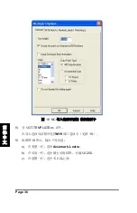
Страница 155: ...Page 35 6 GT TEMPLATE nc a b C ProgramFiles CutWorks SamplesGT TEMPLATE nc c NC 18 7 18 a 1 250 b N c 1 100 in d...

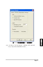
Страница 156: ...Page 36 18 NC 8 GT TEMPLATE nc M19 19 9 19 a Accumark Lectra b 0 250 c...

Страница 157: ...Page 37 19 NC M19 20 11 14 V...

Страница 158: ...Page 38 20 10 21...

Страница 159: ...Page 39 21 11 12 Notcher 22 13 Cut 22 14 22 False 0 00 0 00 N Hits 1...

Страница 160: ...Page 40 22 15 Cut Cut cut 16 Cut 22 17 23 30 00 25 30 00 1 00...

Страница 161: ...Page 41 Map Layers to Tools Cut layer 18 19 18 in 45 72 cm 1 24...

Страница 162: ...Page 42 24 18 1 20 21...

Страница 163: ...Page 43 25 22 23 26 a b c...

Страница 164: ...Page 44 26 24 1 in 2 54 cm 1 in 2 54 cm 25 26 DCS 1500 2500 GERBERcutter...

Страница 165: ...Page 45 C X Y C X Y BCP C GERBERcutter E Stop...

Страница 166: ...Page 46 X Y CutWorks 0 0...

Страница 167: ...Page 47 AccuMark V X0 Y0 X Y C...

Страница 168: ...Page 48 X Y...

Страница 169: ...Page 49 DCS 2500 1 800 321 2448 800 820 1661 InfoJet Inkjet InfoMark 1 75 Theta theta 4...

Страница 170: ...Page 50 1 800 321 2448 800 820 1661 https www gerberscientific net GT eCommerce login aspx 1 10 TL 001 1 75 TL 004 5 30 0 040 TL 051 45 0 020 TL 055 45 0 040 TL 052 55 0 020 TL 166 55 0 040 TL 353 6...

Страница 171: ...Page 51 V 45 3 16 TL 354 45 1 4 TL 257 45 5 16 TL 267 60 3 16 TL 256 7 V 90 0 040 TL 056 8...

Страница 172: ...age 52 1 32 TL 211 1 16 TL 200 3 32 TL 201 1 8 TL 202 3 16 TL 203 1 4 TL 204 9 32 TL 210 5 16 TL 205 3 8 TL 206 1 2 TL 207 9 32 TL 210 1 TL 250 2 TL 251 3 TL 252 4 TL 253 5 TL 254 6 TL 255 10 TL 260 9...

Страница 173: ...60 66 72 78 84 90 96 102 108 114 120 ft 9 1 8 2 4 3 3 6 4 2 m 3 6 8 10 12 14 ft 0 84m 0 86m 33 in 34 in 1 1 m sec 45 ips V PC Windows Gerber ScanVec Assyst Auto Cad Lectra Polygon CutWorks 6 0 to 10 G...

Страница 174: ...Page 54...

Страница 175: ......

Страница 176: ...Corporate Headquarters Gerber Scienti c Inc 24 Industrial Park Road West Tolland CT 06084 USA Tel 1 860 871 8082 Fax 1 860 871 3820 www gerbertechnology com PN 91964002 02 18...

Отзывы: