


SmartSeis
TM
Maintenance Manual
8
3. Once in the Setup menu, for the Halt on field, select to “All, But Keyboard.” Press the
ESC key and exit with saving.
For the “CMOS error” and “BIOS checksum error,” follow steps 1 and 2 and proceed to step
number 4 below.
4. Once in the Setup menu, immediately exit, making sure to save during exit. This will
reset the checksum and should correct the error.
If the errors persist, redo step numbers 1 and 2 and proceed to step number 5 below.
5. Once in the setup menu, verify that the current parameters are correct by comparing
them with the original settings documented on the paperwork sent with the system.
6. Reset the parameters that are different than the original settings. Exit with saving.
If the changes that cause the errors occur again, this is an indication that there is a problem with
the motherboard or with the Lithium backup battery. If changes specifically occur in the LCD
portion of the BIOS setup, the LCD may not be operational. Test this by attaching an external
VGA compatible monitor to the video port on the back of the instrument and repeat the above
instructions.
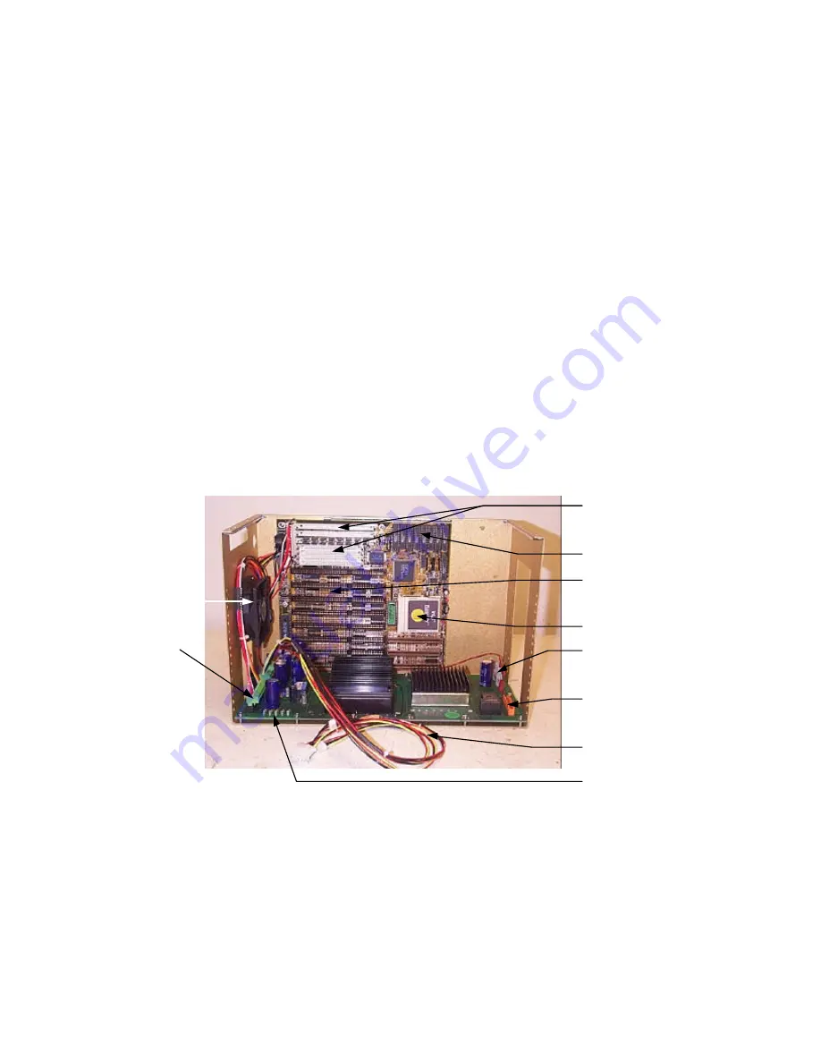
Figure 1. The motherboard (upright) and power board (base).
ISA edge connectors
Motherboard power cable
CPU
Fan
External battery input
power connector
Memory SIMMs
Memory SIMMs
Memory cache
Connectors for
motherboard,
hard and floppy
drives, and
printer power
cables
Power board LEDs
Acquisition board(s)
power connector


