©20
20
, GEOKON. All rights reserved.
Document Revision: A | Release date: 2/2
0
/20
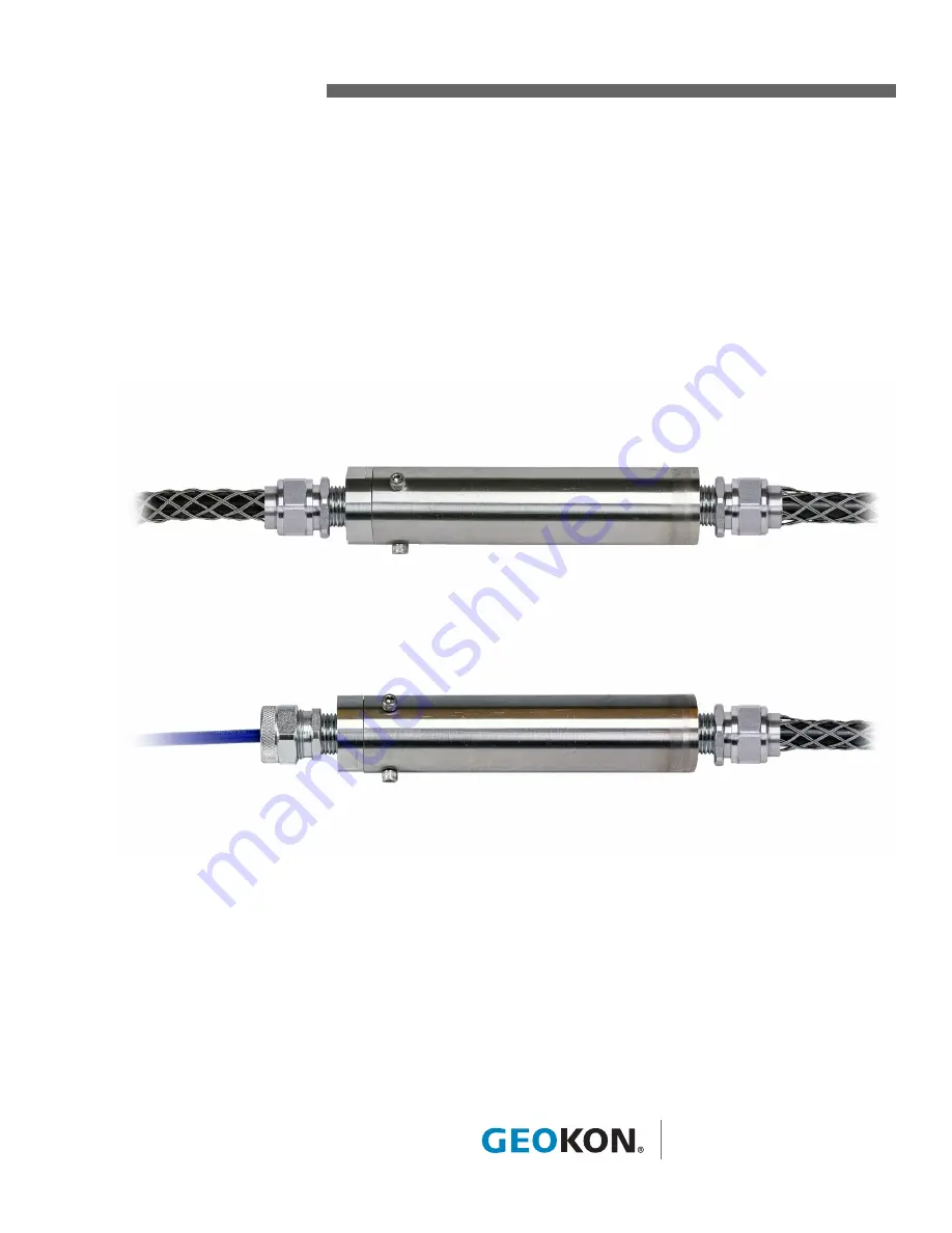
Armored Cable Splice Kit
Model 4500-9-HDF1
Model 4500-9-HDF2
Instruction Manual
Страница 1: ...2020 GEOKON All rights reserved Document Revision A Release date 2 20 20 Armored Cable Splice Kit Model 4500 9 HDF1 Model 4500 9 HDF2 Instruction Manual...
Страница 2: ......
Страница 3: ...N is not responsible for any damages or losses caused to other equipment whether direct indirect incidental special or consequential which the purchaser may experience as a result of the instal lation...
Страница 4: ......
Страница 5: ...ON 2 1 1 1 ARMORED CABLE 2 1 1 2 UNARMORED CABLE 5 1 2 FIXED END PREPARATION 6 2 MAKING THE SPLICE 9 2 1 CONNECT THE WIRES 9 2 2 ADJUST THE SPLICE POSITION 10 2 3 RECONNECT THE FIXED END 10 2 4 ASSEMB...
Страница 6: ...II...
Страница 7: ...figure below FIGURE 2 Model 4500 9 HDF1 Disassembled View FIGURE 3 Model 4500 9 HDF2 Disassembled View The general procedure for making the splice is as follows 1 Position the cables appropriately th...
Страница 8: ...le end cap 1 1 1 ARMORED CABLE Note For preparing blue unarmored cable please refer to Section 1 1 2 1 Slide the black 02 500PEI armored cable through outer end of the Kellems grip and and through the...
Страница 9: ...through the end cap 3 Strip the cable s black outer jacket back approximately 1 40mm from the end to expose the armor and wire leads 4 Bend the exposed armor backward over the outer jacket 5 Remove th...
Страница 10: ...ck approximately 12 mm inch on the red black gauge wires and on the green white thermistor wires Note Do not connect the fitting nut to the connector adapter until you after you have finished splicing...
Страница 11: ...6 unarmored cable through outer end of the Kellems grip and and through the fitting nut 2 Slide the blue cable through the black grommet and end cap 3 Strip the cable s blue outer jacket back approxim...
Страница 12: ...leads Refer to Section 2 for more information For instructions on making the splice see Section 2 1 2 FIXED END PREPARATION 1 Unscrew and remove the cable fitting nut from the fixed end of the tube 2...
Страница 13: ...n through the connector adapter 4 Continue to slide the cable through the tube until it protrudes from the end 5 Strip the cable s black outer jacket back approximately 40 mm 1 5 inches from the end t...
Страница 14: ...e leads and shield wire 10 Strip the insulation back approximately 12 mm inch on the red black gauge wires and on the green white thermistor wires Note Do not connect the fitting nut to the connector...
Страница 15: ...wire leads together color to color including the bare shield wire Alternatively the cable conductors can be soldered together Use the Posi Lock connectors as follows 1 Unscrew and remove the ends fro...
Страница 16: ...ely will have to adjust the Kellems grip and grommet manually to accomodate this Note This step creates slack in the cable inside the tube Note Be careful not to disrupt the spliced wire leads 2 On th...
Страница 17: ...tting nut over the grommet and screw it onto the adapter connector Note Make sure the cable doesn t move during this step Note Do not connect the assembled removable end cap to the tube until you have...
Страница 18: ...the heat sealed wide end of the tube 8 Remove the white wafer from the tube using the provided wooden paddle 9 Stir vigorously with the paddle for one minute to help blend the two components Once the...
Страница 19: ...ARMORED CABLE SPLICE KIT MODELS 4500 9 HDF1 AND 4500 9 HDF2 ENCAPSULANT MIXING INSTRUCTIONS 13 Allow 2 hours minimum for the epoxy to cure before installing...
Страница 20: ......
Страница 21: ......
Страница 22: ......
Страница 23: ......
Страница 24: ...GEOKON 48 Spencer Street Lebanon New Hampshire 03766 USA Phone 1 603 448 1562 Email info geokon com Website www geokon com GEOKON is an ISO 9001 2015 registered company...