17
4.2 Temperature Correction
Geokon’s Vibrating Wire Displacement Transducers have a small coefficient of thermal
expansion; therefore, in most cases correction may not be necessary. However, if maximum
accuracy is desired, or the temperature changes are extreme (>10° C), a correction may be
applied based on the following equation:
Dcorrected = ((R
1
- R
0
)
×
G) + ((T
1
- T
0
)
×
K)
Equation 3 - Thermally Corrected Displacement Calculation
Where;
R
1
is the current reading.
R
0
is the initial reading.
G is the calibration Factor.
T
1
is the current temperature.
T
0
is the initial temperature.
K is the thermal coefficient (see Equation 4).
Tests have determined that the thermal coefficient,
K
, changes with the position of the transducer
shaft. Hence, the first step in the temperature correction process is to determine the proper
thermal coefficient based on the following equation:
K = ((R
1
×
TM)
+
TB)
×
G
Equation 4 - Thermal Coefficient Calculation
Where;
R
1
is the current reading.
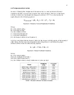
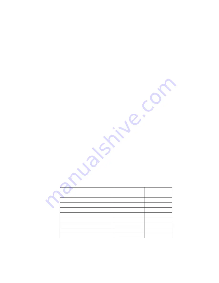
TM is the multiplier from Table 3.
TB is the constant from Table 3.
G is the calibration factor, usually millimeters or inches per digit.
Model
Multiplier
(TM)
Constant
(TB)
4450-3 mm / 4450-0.125”
0.000520
3.567
4450-12 mm / 4450-0.5”
0.000375
1.08
4450-25 mm / 4450-1”
0.000369
0.572
4450-50 mm / 4450-2”
0.000376
0.328
4450-100 mm / 4450-4”
0.000398
0.0864
4450-150 mm / 4450-6”
0.000384
-0.3482
4450-200 mm / 4450-8”
0.000396
-0.4428
4450-300 mm / 4450-12”
0.000424
-0.6778
Table 3 - Thermal Coefficient Calculation Constants
Содержание 4450
Страница 2: ......
Страница 4: ......
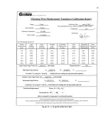
Страница 19: ...19 Figure 11 A Typical Calibration Sheet ...
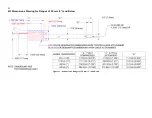
Страница 24: ...24 B 3 Dimensions Drawing for Ranges of 50 mm 2 and Below Figure 12 Dimensions Ranges of 50 mm 2 and Below ...
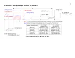
Страница 25: ...25 B 4 Dimensions Drawing for Ranges of 100 mm 4 and Above Figure 13 Dimensions Ranges of 100 mm 4 and Above ...

