13
3. TAKING READINGS
3.1 GK-404 Readout Box
The Model GK-404 Vibrating Wire Readout is a portable, low-power, handheld unit that is
capable of running for more than 20 hours continuously on two AA batteries. It is designed for
the readout of all Geokon vibrating wire gages and transducers, and is capable of displaying the
reading in either digits, frequency (Hz), period (µs), or microstrain (µε). The GK-404 also
displays the temperature of the transducer (embedded thermistor) with a resolution of 0.1 °C.
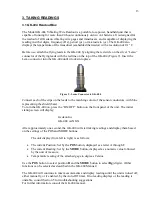
Before use, attach the flying leads to the GK-404 by aligning the red circle on the silver “Lemo”
connector of the flying leads with the red line on the top of the GK-404 (Figure 9). Insert the
Lemo connector into the GK-404 until it locks into place.
Figure 9 - Lemo Connector to GK-404
Connect each of the clips on the leads to the matching colors of the sensor conductors, with blue
representing the shield (bare).
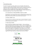
To turn the GK-404 on, press the “ON/OFF” button on the front panel of the unit. The initial
startup screen will display:
Geokon Inc.
GK-404 verX.XX
After approximately one second, the GK-404 will start taking readings and display them based
on the settings of the POS and MODE buttons.
The unit display (from left to right) is as follows:
•
The current Position: Set by the
POS
button, displayed as a letter A through F.
•
The current Reading: Set by the
MODE
button, displayed as a numeric value followed
by the unit of measure.
•
Temperature reading of the attached gage in degrees Celsius.
Use the
POS
button to select position
B
and the
MODE
button to select
Dg
(digits). (Other
functions can be selected as described in the GK-404 Manual.)
The GK-404 will continue to take measurements and display readings until the unit is turned off,
either manually, or if enabled, by the Auto-Off timer. If no reading displays or the reading is
unstable, consult Section 5 for troubleshooting suggestions.
For further information, consult the GK-404 manual.
Содержание 4450
Страница 2: ......
Страница 4: ......
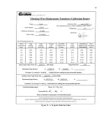
Страница 19: ...19 Figure 11 A Typical Calibration Sheet ...
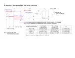
Страница 24: ...24 B 3 Dimensions Drawing for Ranges of 50 mm 2 and Below Figure 12 Dimensions Ranges of 50 mm 2 and Below ...
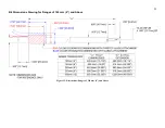
Страница 25: ...25 B 4 Dimensions Drawing for Ranges of 100 mm 4 and Above Figure 13 Dimensions Ranges of 100 mm 4 and Above ...


