8
4)
A check of electrical continuity can be made using an ohmmeter. The resistance between the
two lead wires (usually red and black) should be around 180 ohms. Remember to add the
cable resistance at approximately 14.7
Ω
/1000' or 48.5
Ω
/km at 20 °C. Multiply this factor by
two to account for both directions.
5)
Using an ohmmeter check the resistance between the two thermistor wires (usually white and
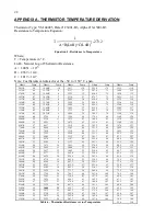
green). Using Table 6 in Appendix A, convert the resistance to temperature. Compare the
result to the current ambient temperature.
6)
Resistance between any conductor and the shield should exceed two megohms.
2.2 Displacement Transducer Installation
1)
Be sure to place the alignment pin of the transducer shaft into the alignment slot during
installation. This will prevent the internal wire from twisting.
2)
With the #10-32 thread of the transducer shaft pressed against the shaft-mounting device,
rotate the transducer approximately 16 turns to tighten the transducer shaft onto the mounting
device.
3)
Attach the red and black gage leads to the readout box. Select position B. (See Section 3 for
readout instructions.)
4)
Gently pull on the transducer housing until the desired reading is obtained, see Table 1.
Do
not extend the shaft further than the range of the gage!
The transducer also may be
damaged if it is allowed to free fall through its stroke.
5)
Hold the desired reading and secure the cable side of the gage against or inside the mounting
device. The transducer can be secured by using a Swagelok male connector with nylon front
and back ferrules. Tighten the Swagelok connector per the instructions in Section 2.3.
Do not
rotate the gage tube relative to the shaft while securing!
6)
Initial readings must be taken and carefully recorded along with the temperature at the time
of installation. These readings serve as a reference for subsequent deformation calculations.
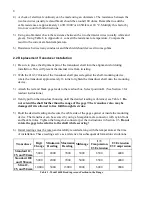
Transducer
Digit
Change
Minimum
Reading
Maximum
Reading
Midrange
1/3
Compression
1/3 Extension
1/3 Extension
1/3 Compression
Standard 12,
25, and 50 mm
5,000
2000
7000
5000
6500
4000
Standard 100
and 150 mm
5,000
2000
7000
5000
6500
4000
Slim 12,
25, and 50 mm
10,000
3000
13000
8000
6000
9000
Table 1 - Model 4450 Reading versus Position in the Range
Содержание 4450
Страница 2: ......
Страница 4: ......
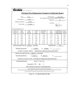
Страница 19: ...19 Figure 11 A Typical Calibration Sheet ...
Страница 24: ...24 B 3 Dimensions Drawing for Ranges of 50 mm 2 and Below Figure 12 Dimensions Ranges of 50 mm 2 and Below ...
Страница 25: ...25 B 4 Dimensions Drawing for Ranges of 100 mm 4 and Above Figure 13 Dimensions Ranges of 100 mm 4 and Above ...


