7
1. INTRODUCTION
1.1 Theory of Operation
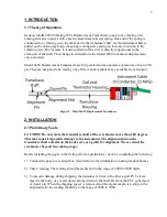
Geokon Model 4450 Vibrating Wire Displacement Transducers consist of a vibrating wire
sensing element, in series with a heat treated, stress relieved spring. One end of the spring is
connected to a vibrating wire, the other end to the transducer shaft. As the transducer shaft is
pulled out from the gage body, the spring is elongated, causing an increase in tension in the
vibrating wire. The increase in tension (strain) of the wire is directly proportional to the
extension of the shaft. This change in strain allows the Model 4450 to measure displacement
very accurately.
Model 4450 Displacement Transducers are fully sealed and can operate at pressures of up to 250
psi. They are designed to be read by one of the various readout boxes available from Geokon.
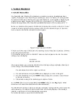
Figure 1 - Model 4450 Displacement Transducer
2. INSTALLATION
2.1 Preliminary Tests
CAUTION!
Do not rotate the transducer shaft of the crackmeter more than 180 degrees.
This may cause irreparable damage to the instrument. The alignment pin on the
transducer shaft and slot on the body serve as a guide for alignment. Never extend the
crackmeter beyond its working range.
Before installing the gages in the field, perform a preliminary check by completing the following
1)
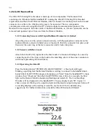
Connect the gage to a readout box. (See Section 3 for information on using readout boxes.)
2)
Take a reading. The reading should be stable and in the range of 4000 to 5000 digits.
3)
To prevent damage during shipping, the transducer arrives with either a split PVC sleeve
taped to the body, or a metal dowel pin inserted into the shaft. Remove the PVC split sleeve
or dowel pin. When the shipping spacer is removed and the alignment pin is resting in the
alignment slot the reading should be in the range of 2000 to 3000.
Содержание 4450
Страница 2: ......
Страница 4: ......
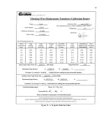
Страница 19: ...19 Figure 11 A Typical Calibration Sheet ...
Страница 24: ...24 B 3 Dimensions Drawing for Ranges of 50 mm 2 and Below Figure 12 Dimensions Ranges of 50 mm 2 and Below ...
Страница 25: ...25 B 4 Dimensions Drawing for Ranges of 100 mm 4 and Above Figure 13 Dimensions Ranges of 100 mm 4 and Above ...


