background image


Page 41/48 

© Geobrugg AG, CH-8590 Romanshorn, Switzerland 

GBE-100A-R / 08 

01


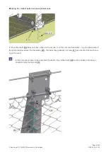
2 pcs.  Spiral rope anchor 

67


2 pcs.  Intermediate anchor rope 

72


2 pcs.  Lower support rope 

84


2 pcs.  3/4" shackle 

94


3 pcs. 

9/16” wire rope clip per rope 

67 

94 

72 

84 

01 


Содержание GBE-100A-R

Страница 1: ...0 2 5 m Test Certificate No S 14 6 Federal Office for the Environment FOEN Switzerland Attending testing institute Swiss Federal Institute for Forest Snow and Landscape Research WSL Birmensdorf Switze...

Страница 2: ...Page 2 48 Geobrugg AG CH 8590 Romanshorn Switzerland GBE 100A R 08...

Страница 3: ...Page 3 48 Geobrugg AG CH 8590 Romanshorn Switzerland GBE 100A R 08...

Страница 4: ...nual is divided into the following parts Proof of quality assurance Stake out Assembly details System overview rope routing ISO 9001 certificate This document makes no claim as to its completeness It...

Страница 5: ...which IQNet belongs The Quality Manual provides complete information on how individual system parts primary material commercial products and end products must undergo extensive testing to rule out in...

Страница 6: ...imensioning basis or non usage of standard components systems or original parts but also by corrosion caused by environmental pollution or oth er human factors as well as other external influences The...

Страница 7: ...NG ON THE TERRAIN 12 5 STAKE OUT GEOMETRY 14 6 ROPE ANCHOR PLACEMENT 18 7 ANCHORING THE POSTS AND ROPE ANCHORS 19 8 PREPARING THE MESHES AND POSTS 21 9 INSTALLATION BY CRANE OR HELICOPTER 24 10 INSTAL...

Страница 8: ...lope 1 HAZARD WARNINGS GROUP MANAGER QUALIFICATION Only a qualified group manager is permitted to manage the installation process ROPES UNDER TENSION Ropes are under tension Ensure that no one is stan...

Страница 9: ...rench range 25 400 Nm see tightening torque required for wire rope clips and base plate fastening nuts Open ended wrench for base plate fastening nuts Felco C16 or C112 wire rope cutter or similar 12...

Страница 10: ...next to the thimble For loops without a thimble the length h between the first wire rope clip and the point of load incidence must minimally be 15 time the nominal diameter of the rope In unloaded co...

Страница 11: ...14 15 9 16 3 50 150 24 A visible contusion of the wire ropes positively indicates that the wire rope clips have been tightened to the required tightening torque Undamaged wire rope clips could be reus...

Страница 12: ...are detected Structure line In principle you must plan the line of the structure so that is as straight and horizontal as possible Wherever possible avoid or compensate for irregular line routing and...

Страница 13: ...Mesh length adjustment h Height difference between two neighbouring posts Table 2 Post spacing 6 8 m 8 10 m 10 12 m h 1 00 m 1 50 m 2 00 m No change necessary h 1 00 m 1 50 m 2 00 m Mesh must be adap...

Страница 14: ...rain Depending on the terrain it may not be possible to follow standard stake out procedure Making lots of small ad aptations to the cross section or lengths of nets ropes posts and so on is sufficien...

Страница 15: ...ANCHOR FOR INTERMEDIATE ANCHOR 1 a x A B C h c c a a Z Z h a c e 2 00 3 00 0 30 1 00 2 50 3 75 0 30 1 25 3 00 4 50 0 30 1 50 Length h Structure height x Post spacing Anchor point A Upper support rope...

Страница 16: ...ost The downslope anchor has a rope diameter d of 12 mm INTERMEDIATEANCHOR e T 5 y 15 1 x 2 When a change in alignment downslope is greater than 15 intermediate anchors must be arranged whereby the do...

Страница 17: ...en changes in alignment downslope are greater than 25 a support rope separation must also be arranged for the intermediate anchor CHANGE IN ALIGNMENT UPSLOPE When a change in alignment upslope is grea...

Страница 18: ...MENT Depending on the terrain conditions but in any case if terrain slope angle 45 it is recommended to use gap filling nets additional mesh between the terrain and bottom part of the mesh The anchor...

Страница 19: ...t fix the anchors 05 in place in loose ground 110 Fill in the concrete foundation 111 Tighten the fastening nuts 10 to a preload force of approx 30 kN Concrete Applicable to all ground and rock types...

Страница 20: ...r an anchor preload force of approx 30 kN Swiss GEWI NG 20 Swiss GEWI NG 25 Swiss GEWI NG 28 Tightening torque 200 Nm 300 Nm 400 Nm Use grout that is resistant to frost and de icing salts Reinforcemen...

Страница 21: ...DLE The posts are numbered from left to right from downslope up S As standard the mesh bundle is attached to the right of the post X If there are greater height differences it is easier to pull the me...

Страница 22: ...eight of 2 5 m and 3 m 31 1 Middle post for a structure height of 2 m 31 2 Middle post for a structure height of 2 5 m and 3 m 83 7 pcs 5 8 shackle for 30 1 and 30 2 83 4 pcs 5 8 shackle for 31 1 and...

Страница 23: ...at are to be left free on the left and right of the mesh are al ready held out of the way for the support rope 202 by the guide profiles The height of the topmost row of diamonds 203 or the guide prof...

Страница 24: ...rugg AG CH 8590 Romanshorn Switzerland GBE 100A R 08 9 INSTALLATION BY CRANE OR HELICOPTER Securely fasten the mesh bundles with tape 204 Use the middle 5 8 shackle 83 at the top of the post to lift t...

Страница 25: ...llation steps for a standard installation Descriptions of the corresponding details can be found further on in the manual Anchors are drilled and foundations completed Set the posts that come pre asse...

Страница 26: ...see further steps Route the lower support cable from one lateral anchor through the shackle at the bottom of the post and the guide tubes in the mesh bundle to the other lateral anchor but do not ten...

Страница 27: ...Page 27 48 Geobrugg AG CH 8590 Romanshorn Switzerland GBE 100A R 08 Tension the lower support rope Close the flex zones...

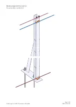
Страница 28: ...t upslope using the bolt head so that the mesh or the horizontal helix springs do not catch on the bolt head 67 1 pc Lateralanchor rope 69 1 pc Vertical rope 71 1 pc Upper support rope 72 1 pc Lower s...

Страница 29: ...e 29 48 Geobrugg AG CH 8590 Romanshorn Switzerland GBE 100A R 08 Mount the vertical ropes 69 on the side facing the lateral anchors 69 69 Structure height of 2 5 m and 3 m The post profile is an HEA 1...

Страница 30: ...n the bolt head 71 1 pc Upper support rope 72 1 pc Lower support rope 76 1 pc Post top rope 83 4 pcs 5 8 shackle 93 2 pcs 7 16 wire rope clip Tightening torque lubricated 80 Nm unlubricated 215 Nm 72...

Страница 31: ...Page 31 48 Geobrugg AG CH 8590 Romanshorn Switzerland GBE 100A R 08 Structure height of 2 5 m and 3 m The post profile is an HEA 140...

Страница 32: ...itzerland GBE 100A R 08 LATERALANCHOR ROPE UPPER AND LOWER SUPPORT ROPE ON THE LEFT ROPE AN CHOR 67 1 pc Lateral anchor rope 72 1 pc Lower support rope 73 1 pc Upper support rope 84 2 pcs 3 4 shackle...

Страница 33: ...0A R 08 LATERAL ANCHOR ROPE UPPER AND LOWER SUPPORT ROPE ON THE RIGHT ROPE AN CHOR 67 1 pc Lateral anchor rope 72 1 pc Lower support rope 73 1 pc Upper support rope 94 3 pcs 9 16 wire rope clip per ro...

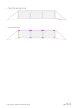
Страница 34: ...of each post see next chapter The distance between the ground and the upper support rope is 30 cm greater than the structure height for the posts 302 Structure height of 2 m 1 pc Helix 2200 x 64 4 10...

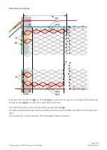
Страница 35: ...ix 3500 x 64 4 90 is cut in half or quarters on site Flex zones for middle posts In the area of the 10 diamonds 206 the first helix 304 1 is wound into the upper support rope The second helix 304 2 is...

Страница 36: ...helix 304 2 is wound into the mesh and the first helix 207 The helix 304 1 is not wound into the support rope between the two shackles that the lower support rope is routed through The bottommost and...

Страница 37: ...y The second helix 304 4 is wound into the mesh and the first helix The edge of the mesh is wound into the vertical rope with the helix 302 The topmost and the third topmost diamond or the bottommost...

Страница 38: ...e a base on the terrain or on the concrete foundation e g the base plate of the post protrudes above the foundation 210 the helix may gradually unscrew 211 as a result of the mesh mov ing in the wind...

Страница 39: ...ugg AG CH 8590 Romanshorn Switzerland GBE 100A R 08 DOWNSLOPE ANCHOR ROPE 83 79 94 01 01 2 pcs Spiral rope anchor 67 2 pcs Downslope Anchor rope 83 2 pcs 5 8 shackle in addition 94 3 pcs 7 16 wire rop...

Страница 40: ...witzerland GBE 100A R 08 12 SUPPORT ROPE SEPARATION WITH INTERMEDIATE ANCHOR ROPE 76 71 67 83 72 67 2 pcs Intermediate anchor rope 71 2 pcs Upper support rope 72 2 pcs Lower support rope 76 2 pcs Post...

Страница 41: ...ugg AG CH 8590 Romanshorn Switzerland GBE 100A R 08 01 2 pcs Spiral rope anchor 67 2 pcs Intermediate anchor rope 72 2 pcs Lower support rope 84 2 pcs 3 4 shackle 94 3 pcs 9 16 wire rope clip per rope...

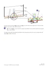
Страница 42: ...ower support rope respectively The second helix 304 2 is wound into the mesh and the first helix 207 The helix 304 1 is not wound into the support rope between the two shackles that the lower support...

Страница 43: ...dard you can consult with Geobrugg AG to develop a strut solution ROCK CONNECTION If standard stake out is not possible you can consult with Geobrugg AG to develop a rock connection var iant GULLY SOL...

Страница 44: ...ttom shackle pointing upslope PICTURE d Have the correct number of diamonds been left free on the right and left of the posts e Is the mesh correctly attached to the support ropes f Is the number of w...

Страница 45: ...Page 45 48 Geobrugg AG CH 8590 Romanshorn Switzerland GBE 100A R 08...

Страница 46: ...Page 46 48 Geobrugg AG CH 8590 Romanshorn Switzerland GBE 100A R 08...

Страница 47: ...Page 47 48 Geobrugg AG CH 8590 Romanshorn Switzerland GBE 100A R 08...

Страница 48: ...Page 48 48 Geobrugg AG CH 8590 Romanshorn Switzerland GBE 100A R 08 EXCERPT FROM THE FOEN TEST CERTIFICATE NO S 14 6...

Отзывы: