Geobrugg GBE-1000A Скачать руководство пользователя страница 5


Page 5/41 

© Geobrugg AG, CH-8590 Romanshorn, Switzerland 

GBE-1000A / 16 

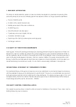
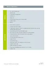
I  RANGE OF APPLICATION 


The design of rockfall protection systems is based on detailed investigations by specialized engineering firms, 

particularly taking into account the following geotechnical aspects to define the range of possible applications:


  Previous Rockfall events 

  Condition of the rockfall breakout zone 

  Stability assessment of the entire rockfall zone 

  Rockfall frequency 

  Size of the blocks to be intercepted 

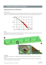
  Trajectories and bounce heights of stones 

  Calculation of kinetic energies 

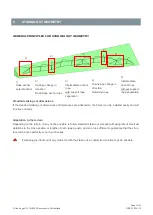
  Positioning of the barrier (considering the local topography) 

  Anchorage conditions 


II  QUALITY OF THE SYSTEM COMPONENTS 


Geobrugg AG, formerly the Geobrugg Schutzsysteme (Geobrugg Protection Systems) department of Fatzer AG, 

Romanshorn, has been certified according to the quality management system requirements (ISO 9001:2008) un-

der the registration number CH-34372 since August 22nd, 1995. The certification center is the SQS (Swiss Asso-

ciation for Quality and Management Systems), which is a member of IQNet. The quality manual specifies in full 

the way in which the individual system components (basic material, commercial products, and end products) are 

checked extensively to eliminate poor quality. You can find the corresponding certificates in the appendix. 


III FUNCTIONAL EFFICIENCY OF THE BARRIER SYSTEMS 


The functional efficiency of the system is based on one-to-one rockfall tests, carried out and tested in accordance 

with the guidelines for approval of rockfall protection nets ETAG 027. The one-to-one rockfall tests are carried out 

by dropping a block vertically into the middle field of a three-field barrier. The distance between posts is 10 m, and 

an impact velocity of 25 m/s is reached. The full-scale test is approved by a notified test body and the European 

Technical Approval (ETA) has the number ETA 

– 09/0262. 


IV QUALITY CONTROL FOR INSTALLATION 


This  product  manual  describes  in  detail  the  different  steps  for  installation  of  the  barriers.  These  steps  must  be 

faithfully followed by local contractors. 

Содержание GBE-1000A

Страница 1: ...y A Energy class 3 1000 kJ Height 4 5 m Attending testing institute Swiss Federal Institute for Forest Snow and Landscape Research WSL Birmensdorf Switzerland Date 08 10 2018 Edition 16 Geobrugg AG CH...

Страница 2: ...Page 2 41 Geobrugg AG CH 8590 Romanshorn Switzerland GBE 1000A 16...

Страница 3: ...Page 3 41 Geobrugg AG CH 8590 Romanshorn Switzerland GBE 1000A 16...

Страница 4: ...ide Staking out Assembly details ISO 9001 certificate This document does not claim to be exhaustive Before starting an installation it must be ensured that the copy of the product manual is up to date...

Страница 5: ...22nd 1995 The certification center is the SQS Swiss Asso ciation for Quality and Management Systems which is a member of IQNet The quality manual specifies in full the way in which the individual sys...

Страница 6: ...s natural disasters inadequate dimensioning or failure to use standard components systems and original parts but also through corrosion caused by environmental pollu tion or other man made factors as...

Страница 7: ...OPE CLIPS 10 4 STAKING OUT DEPENDING ON THE TERRAIN 12 5 STAKING OUT GEOMETRY 14 6 ROPE ANCHOR PLACEMENT 18 7 ANCHORING THE BASE PLATE 19 8 PREPARING THE POSTS AND NETS 22 9 IN CASE OF CRANE OR HELICO...

Страница 8: ...wnslope 1 HAZARD STATEMENT QUALIFICATION OF THE GROUP LEADER The management of installation may only be done by a qualified group leader CABLES WITH PRETENSION Cables are under tension During installa...

Страница 9: ...400 Nm see tightening torque required for wire rope clips and base plate fastening nuts Open ended wrench for base plate fastening nuts Felco C16 or C112 wire rope cutter or similar 12 mm cutting capa...

Страница 10: ...next to the thimble For loops without a thimble the length h between the first wire rope clip and the point of load incidence must minimally be 15 time the nominal diameter of the rope In unloaded con...

Страница 11: ...18 20 3 4 4 90 180 27 A visible contusion of the wire ropes positively indicates that the wire rope clips have been tightened to the required tightening torque Undamaged wire rope clips could be reuse...

Страница 12: ...ormation on bounce heights and where shadowing may occur Lining Where possible the barrier should be installed so that is in a straight line and that all posts are at the same level horizontally This...

Страница 13: ...ion of length of the mesh h difference in height between two neighbouring posts Tab 2 Post distance 6 8 m 8 10 m 10 12 m h 0 50 m 1 00 m 1 50 m No adjustment necessary h 0 50 m 1 00 m 1 50 m Net must...

Страница 14: ...low standard stake out procedure Making lots of small ad aptations to the cross section or lengths of nets ropes posts and so on is sufficient to guarantee that the struc ture will function perfectly...

Страница 15: ...ion tolerance 0 20 m h a c d 1 e 3 00 4 50 1 00 5 10 1 50 4 00 6 00 1 30 6 80 2 00 5 00 7 50 1 65 8 50 2 50 1 In a ground slope of less than 30 the distance between post and retaing rope anchor is mod...

Страница 16: ...downslope anchor rope has a rope diameter of d 16 mm Length e see Tab 3 x post distance y angle of change in direction Anchor point T downslope anchor rope 2 e T x 2 5 y 15 1 x 2 x 2 Intermediate anc...

Страница 17: ...ort rope separation is to install in addition to the intermediate suspension DOWNSLOPE CHANGE IN DIRECTION For a downslope change in direction of more than 30 an additional retaining rope D is mounted...

Страница 18: ...le between retaining rope and post inclination of the ground plate etc Depending on the terrain conditions but in any case if terrain slope angle 45 it is recommended to use bavettes additional mesh b...

Страница 19: ...and install securing anchor 06 by using the base plate as tem plate Length min 1 0 m Fill in the concrete foundation 111 Tighten the fastening nuts 10 to approx 30 kN pretensioning force CONCRETE Can...

Страница 20: ...Drill holes for the anchors vertical and inclined 45 to the base plate to accommodate inclined anchors Prepare the concrete foundation 111 the concrete foundation 111 is dimensioned and reinforced in...

Страница 21: ...rtar in the anchor 08 the project engineer calculates the lengths of the anchors Position the base plate 29 in the levelling layer of mortar Tighten the fastening nuts 10 with the spacers 09 to approx...

Страница 22: ...top and 11 meshes on the bottom of the net panel are marked that means the meshes are free The support rope is not guided through the meshes VIEW A A 33 83 67 83 66 83 42 39 33 1 Stk running wheel wit...

Страница 23: ...running wheels The mounting bracket 202 is placed at the correct height between the rungs 203 and the post wall The net bundle is placed on the mounting bracket and securely fastened with 204 bands 11...

Страница 24: ...rom left to right viewed from the valley side S The mesh bundles are mounted on the right of the post as standard X If there are large differences in height it is easier to pull the mesh down from the...

Страница 25: ...00A 16 9 IN CASE OF CRANE OR HELICOPTER INSTALLATION Fasten the mesh bundle using bands 204 and the mounting bracket 202 so that it cannot fly away Use the centre 5 8 shackle on the top of the post 20...

Страница 26: ...tion should be exercised as posts can still flip over backwards Install the lateral ropes and intermediate anchor ropes Install the U Brake for the top support rope on the anchors Guide the top suppor...

Страница 27: ...Page 27 41 Geobrugg AG CH 8590 Romanshorn Switzerland GBE 1000A 16 Install the vertical ropes close to the two outermost posts The support ropes go through the meshes except next to the post...

Страница 28: ...Romanshorn Switzerland GBE 1000A 16 11 ASSEMBLY DETAILS ROPE CONNECTION TO THE ANCHORS RETAINING ROPES ON THE UPSLOPE ANCHORS 01 1 pcs Spiral rope anchor 66 1 pcs Retaining rope 96 3 pcs Wire rope cl...

Страница 29: ...cs running wheel with straight shackle 1 56 1 pcs hexagonal bolt M20x110 57 2 pcs washer M20 58 1 pcs hexagonal nut M20 66 2 pcs Retaining rope 67 1 pcs Lateral rope 69 1 pcs Vertical rope 71 1 pcs To...

Страница 30: ...separation the overturn securing rope 68 is installed temporary It is a schematic illustration of the net bundle make sure that the right number of meshes rest free 33 2 pcs running wheel 56 1 pcs hex...

Страница 31: ...16 LATERAL ROPE AND BOTTOM SUPPORT ROPE ON THE ROPE ANCHOR 01 1 pcs spirale rope anchor 45 1 pcs U Brake U 300 Type 60 8 84 2 pcs shackle 3 4 94 3 pcs wire rope clip 9 16 per rope 96 4 pcs wire rope...

Страница 32: ...Page 32 41 Geobrugg AG CH 8590 Romanshorn Switzerland GBE 1000A 16 TOP SUPPORT ROPE ON THE ROPE ANCHOR 71 84 84 45 01 96 84 01 45 84 71...

Страница 33: ...Page 33 41 Geobrugg AG CH 8590 Romanshorn Switzerland GBE 1000A 16 TECCO G80 4 ON THE SUPPORT ROPES MIDDLE POST 1 2 3 4 5 6 7 8 9 10 11 11 loops free 1 2 3 4 5 6 7 8 9 10 11 11 loops free 80 34 34...

Страница 34: ...E SUPPORT ROPES BORDER POST 34 34 11 10 9 8 7 6 5 4 3 2 1 11 10 9 8 7 6 5 4 3 2 1 82 82 11 loops free 11 loops free 34 Mount 4 round clips on both the left and right of the post starting with the post...

Страница 35: ...on always contains intermediate anchor ropes In case of a support rope separation the overturn securing rope 68 is installed temporary 86 45 72 86 83 67 72 83 67 33 87 45 45 2 pcs U Brake U 300 Type 6...

Страница 36: ...n Switzerland GBE 1000A 16 INTERMEDIATE ROPE SUSPENSION VALLEY SIDE ANCHORING 01 1 pcs Spiral rope anchor 79 1 pcs Downslope anchor ropes 83 1 pcs Shackle 5 8 94 3 pcs Wire rope clip 9 16 95 3 pcs Wir...

Страница 37: ...tion with Geobrugg AG ROCK FACE CONNENCTION If it is not possible to use the standard staking out procedure an option for solid rock can be developed in consultation with Geobrugg AG This also involve...

Страница 38: ...led correctly c Have the correct number of loops been left free on the left and right of the posts d Is the net correctly fastened to the support ropes e Have the correct number of wire rope clips bee...

Страница 39: ...Page 39 41 Geobrugg AG CH 8590 Romanshorn Switzerland GBE 1000A 16...

Страница 40: ...Page 40 41 Geobrugg AG CH 8590 Romanshorn Switzerland GBE 1000A 16...

Страница 41: ...Page 41 41 Geobrugg AG CH 8590 Romanshorn Switzerland GBE 1000A 16...

Отзывы: