


Page 35/41
© Geobrugg AG, CH-8590 Romanshorn, Switzerland
GBE-1000A / 16
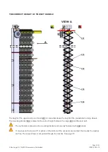
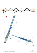
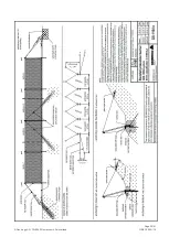
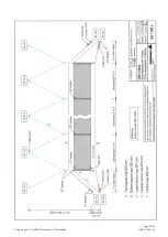
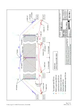
SUPPORT ROPE SEPARATION
A support rope separation always contains intermediate anchor ropes.
In case of a support rope separation, the overturn securing rope
68
is installed temporary.
86
45
72
86
83
67
72
83
67
33,87
45
45
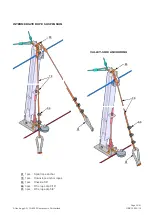
2 pcs
U-Brake U-300-Type 60-8
309
1 pcs Structural Bolt M24x110
67
2 pcs
intermediate suspension
83
3 pcs
shackle
5/8“
86
4 pcs
shackle 1
“
309
Содержание GBE-1000A
Страница 2: ...Page 2 41 Geobrugg AG CH 8590 Romanshorn Switzerland GBE 1000A 16...
Страница 3: ...Page 3 41 Geobrugg AG CH 8590 Romanshorn Switzerland GBE 1000A 16...
Страница 39: ...Page 39 41 Geobrugg AG CH 8590 Romanshorn Switzerland GBE 1000A 16...
Страница 40: ...Page 40 41 Geobrugg AG CH 8590 Romanshorn Switzerland GBE 1000A 16...
Страница 41: ...Page 41 41 Geobrugg AG CH 8590 Romanshorn Switzerland GBE 1000A 16...


