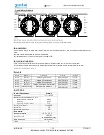
CAUTION: A jumper card is provided to test for correct wiring in the supervisory mode only. DO NOT pass alarm current through the jumper.
NOTE:
All strobes are designed to flash as specified with continuous applied voltage. This appliance is not recommended for use on coded or pulsing
signaling circuits. However, use of the AVS44 control module is permitted to synchronize the strobe and/or mute the horn.
IV. WIRING
Wiring for independent synchronized strobes and horn.
Using this method you may:
· Use only two wires to synchronize the temporal horn and strobe with the ability to mute the horn (place switches
1
and
2
up on the GEC).
· Mute the horn only when the temporal horn option has been selected.
Wiring for synchronized parallel (unison) horn/strobe operation.
Using this method you may:
· Use only two wires to synchronize the temporal horn and strobe
without
the ability to mute the horn (place switches
1
and
2
up on the GEC).
· Choose either temporal or continuous horn with the temporal horn synchronized.
· Also wire the control module (AVS44) to only the strobe input power terminals, set the horn to continuous mode and power it from a coded source.
NOTE:
For this option, switches
1
and
2
on the GEC (Fig.1) must be down to isolate power to the audible and visible portion of the circuit.
2
(GEC3 & GES3 ONLY)


