background image

EB-GS2985-S
Evaluation Board User Guide
52246 - 2

July 2009

22 of 25

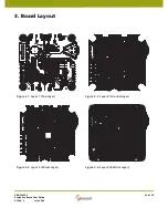
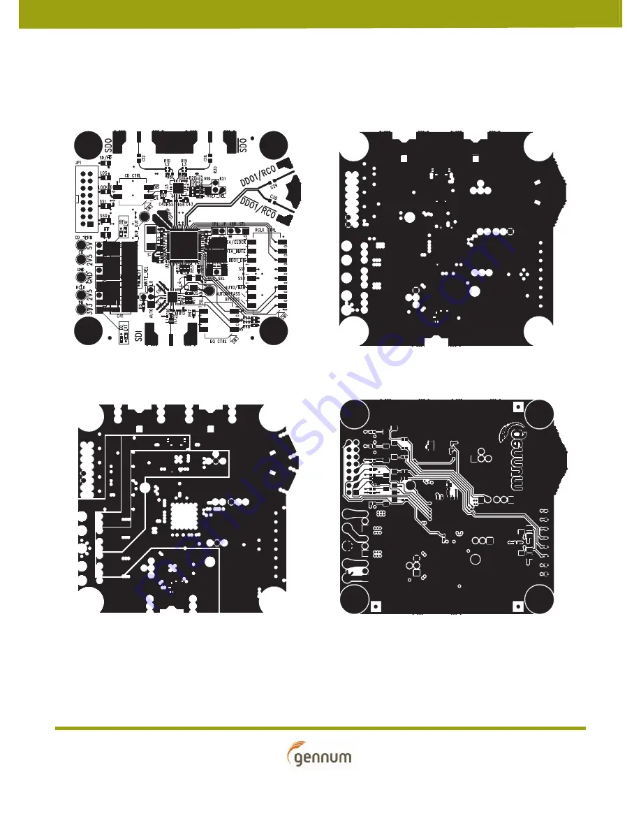
3. Board Layout

Figure 3-1: Layer 1 (Top Layer)

Figure 3-2: Layer 2 (Ground Layer)

Figure 3-3: Layer 3 (Power Layer)

Figure 3-4: Layer 4 (Bottom Layer)

Содержание EB-GS2985-S

Страница 1: ...EB GS2985 S Evaluation Board User Guide 1 of 25 EB GS2985 S Evaluation Board User Guide 52246 2 July 2009 www gennum com...

Страница 2: ...ware 13 1 9 3 Setting Up the Hardware 16 1 9 4 GS2985 Control Software 17 Functionality of Buttons 18 Functionality of Knobs 18 Pin Override Functionality 19 1 9 5 Start up Process 19 1 10 Optional Co...

Страница 3: ...processofthe GS2985 Multi rate SDI Reclocker with Equalization and De emphasis It is strongly recommended to read the GS2985 Data Sheet Doc ID 36663_DocX pdf before using this evaluation kit Evaluatio...

Страница 4: ...e GS2984 3G Equalizer EQ and the GS2988 3G Cable Driver CD The GS2985 is designed to automatically recover the embedded clock from a SMPTE 424M SMPTE 292M or SMPTE 259 C compliant digital video signal...

Страница 5: ...or the EB GS2985 S Figure 1 1 GS2985 Single channel Evaluation Board EB GS2985 S GND SDO SDO SDI DATA1 RCLK Output EQ Control SW3 RCLK Control SW1 KBB Input Select KBB_SEL RSET Resistor Select RSET_SE...

Страница 6: ...cable on JP1 is removed the SPI interface is automatically disabled and the board goes into legacy mode The GS2985 registers will maintain their settings until the board is powered down or reset via t...

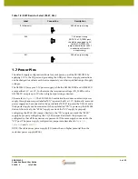
Страница 7: ...1 7 DATA_MUTE Data Mute Data Mute Off Data Mute On 1 8 DATA CLOCK Data Clock select DDO1 DDO1 selected RCO RCO selected 1 Table 1 2 SW1 Positions Switch Position Label Description HIGH 1 LOW 0 Default...

Страница 8: ...Compensation for 6dB flat attenuation No change in gain 0 2 BP Bypass Bypass On Bypass Off 0 3 CM Common Mode Set NOTE CM should be set to 1 when using a 2 5V supply for the Reclocker Output CM set to...

Страница 9: ...connected to the post labelled RCLK to power the GS2985 and a third power supply can be connected to the post labelled CD to power up the GS2988 device Alternatively the RCLK supply can track the EQ...

Страница 10: ...er supply tracks Equalizer supply EXT Reclocker uses a separate power supply RCLK post Table 1 10 Cable Driver Supply Select CD_SEL Position Connection Description RCLK default Cable Driver supply tra...

Страница 11: ...le Board Software Connect the Gennum USB Dongle Board to a Computer Insert one end of the USB cable to the computer USB port and the other end to the Gennum USB Dongle Board The microcontroller will c...

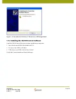
Страница 12: ...Gennum USB Dongle Board 5 Select Include this location and navigate browse to the directory D MCHPFSUSB PC MCHPUSB Driver Release and click Open De Select Search removable media Figure 1 4 Select the...

Страница 13: ...B Dongle Board 1 9 2 Installing the GS2985 Control Software Install the GS2985 Control Software one time installation per computer 1 Insert the Gennum GS2985 Evaluation Board CD 2 Traverse to the GS29...

Страница 14: ...ion Board User Guide 52246 2 July 2009 14 of 25 Figure 1 6 GS2985 Control Welcome Screen You will be prompted to select a directory location to install the GS2985 software Figure 1 7 GS2985 Control Fi...

Страница 15: ...July 2009 15 of 25 The next screen is to verify your choices Figure 1 8 GS2985 Control Ready to Begin Installation Window The window below will appear once the wizard finished the installation Figure...

Страница 16: ...EB GS2985 S Board USB Dongle Board setup When the Gennum USB Dongle Board is connected to the EB GS2985 S the GS2985 automatically switches from Legacy mode to SPI mode As an indicator the HIF LED on...

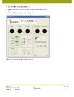
Страница 17: ...de 52246 2 July 2009 17 of 25 1 9 4 GS2985 Control Software 1 Start GS2985 Control Software by clicking on the appropriate link on the Start Menu 2 Control SPI Register Settings Observe Outputs Figure...

Страница 18: ...TA to a GS2985 register x00 x0D ReadStatus Reads status of outputs SS0 SS1 LOS SD HD Locked SS1 and SS0 indicate the selected data rate 00 Reserved 01 270Mbs 10 1485Mbs 11 2970Mbs LOS indicates when a...

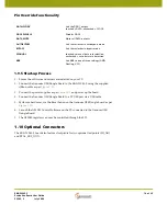
Страница 19: ...n on the Gennum USB Dongle board as per Figure 1 10 6 Launch the GS2985 Control Software on the PC connected to the Gennum USB Dongle Board 7 The GS2985 registers can now be controlled through the SPI...

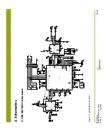
Страница 20: ...J3 BNC VCC_Term GND R15 75R R16 75R C22 10n L3 3n9 GND C18 4u7 R2 49k9 C2 18p VCC2 C9 1u HIF LOW SPI MODE R14 DNP R1 49k9 R55 DNP HIF HIGH LEGACY MODE R56 DNP GND GND CD EQ_EN R5 221R SPI_SCK JP14 LO...

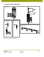
Страница 21: ...46 5k DNP R35 14k Q7 NPN 1 CD 3V3 2V5 R36 14k C41 10u C40 100n 1 GND 1 EQ 3V3 GND VCC1 1 3 2 RCLK_SEL CD_EQ_ENb CD_DISb R31 221R 1 RCLK 3V3 2V5 VCC2 EQ_GAIN_SEL C44 10u EQ_BYPASS C45 100n EQ_CMSET GND...

Страница 22: ...GS2985 S Evaluation Board User Guide 52246 2 July 2009 22 of 25 3 Board Layout Figure 3 1 Layer 1 Top Layer Figure 3 2 Layer 2 Ground Layer Figure 3 3 Layer 3 Power Layer Figure 3 4 Layer 4 Bottom Lay...

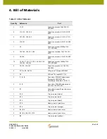
Страница 23: ...5R 0402 13 C5 C6 C7 C8 C11 C13 C20 C22 C24 C25 C26 C30 C32 Capacitor ceramic 10000pF 16V 10 X7R 0402 4 C9 C10 C14 C31 Capacitor ceramic 1 F 10V 10 X5R 0402 5 D1 D2 D3 D4 D6 LED green TSS type SMD 2 03...

Страница 24: ...6W 1 0402 SMD 1 R24 Resistor 267 1 16W 1 0402 SMD 1 R29 Resistor 100 1 16W 1 0402 SMD 6 R32 R33 R34 R35 R36 R39 Resistor 14k 1 16W 1 0402 SMD 3 R5 R31 R47 Resistor 221 1 16W 1 0402 SMD 4 R51 R52 R53 R...

Страница 25: ...num com NORTH AMERICA EASTERN REGION 4281 Harvester Road Burlington Ontario L7L 5M4 Canada Phone 1 905 632 2996 Fax 1 905 632 2055 E mail nae_sales gennum com KOREA 8F Jinnex Lakeview Bldg 65 2 Bangid...

Страница 26: ...Mouser Electronics Authorized Distributor Click to View Pricing Inventory Delivery Lifecycle Information Semtech EBK GS2985 01 EBK GS2985 02...

Отзывы: