background image

August 2018

Part No. 57.4400.9220GT 

GTH-2506 GTH-3007 

2-7 

Section 2 • Specifications

SPECIFICATIONS

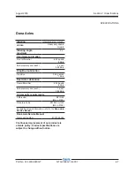
Dana Axles

Steering

Integrated steer cylinder

Joints

Heavy duty double 

U-joints

Steering angle, 

maximum

40 °

Front Axle Lubrication

Front differential

6.34 quarts

6 liters

Axle planetary end (each)

1 quart

0.95 liters

Drop Box Lubrication

Drop Box

0.26 gallons

1 liters

Rear Axle Lubrication

Rear differential

6.34 quarts

6 liters

Axle planetary end (each)

1 quart

0.95 liters

Oil viscosity requirements

Differential

API GL5

(MIL L-2105)

Planetary ends

API GL4 or GL5

(MIL L-2105)

For additional axle information, refer to the 

Dana Axle 

Service Manual

Dana Axle Service Manual

Genie part number

57.4700.0026

Continuous improvement of our products is 

a Genie policy. Product specifications are 

subject to change without notice.

Содержание GTH-2506 Stage A

Страница 1: ...1 Service Manual GTH 2506 Deutz Stage IIIA IIIB Part No 57 4400 9220GT Rev A August 2018 From GTH250619M 1001 Serial Number Range GTH 3007 Deutz Stage IIIA IIIB From GTH300719M 501...

Страница 2: ...t and a suitable workshop In these instances we strongly recommend that maintenance and repair be performed at an authorized dealer service center Technical Publications Genie has endeavored to delive...

Страница 3: ...tial Release REFERENCE EXAMPLES Deutz Engine_Section 2_Specifications A 6 B 3 C 7_Section 3_Maintenance Procedure 3 2 6 4 9 1_Section 4_Repair Procedure Fault Codes_Section 5 6 35 6 56 6 104_Section 6...

Страница 4: ...atic Page Description REFERENCE EXAMPLES Deutz Engine_Section 2_Specifications A 6 B 3 C 7_Section 3_Maintenance Procedure 3 2 6 4 9 1_Section 4_Repair Procedure Fault Codes_Section 5 6 35 6 56 6 104_...

Страница 5: ...r TEREX Global GmbH M hlenstrasse 26 Switzerland INTRODUCTION Serial Number legend GTH 2506 16 M XXXX Model Year of manufacture Facility code Sequence number Serial label located inside chassis Serial...

Страница 6: ...vi GTH 2506 GTH 3007 Part No 57 4400 9220GT August 2018 This page intentionally left blank 1RYHPEHU 7 7 7 7 7 7 3DUW 1R LY 7KLV SDJH LQWHQWLRQDOO OHIW EODQN...

Страница 7: ...s identified in the Operator s Manual are also safety hazards when maintenance and repair procedures are performed Do Not Perform Maintenance Unless You are trained and qualified to perform maintenanc...

Страница 8: ...ive clothing if the situation warrants it Be aware of potential crushing hazards such as moving parts free swinging or unsecured components when lifting or placing loads Always wear approved steel toe...

Страница 9: ...2 2 Hydraulic Specifications 2 3 Hydraulic Component Specifications 2 4 Function Manifold Specifications 2 5 Air Conditioner Refrigerant Specifications 2 5 Deutz TD 2 9 L4 Engine 2 6 Dana Axles 2 7 H...

Страница 10: ...ricate the Boom 3 7 A 5 Perform Engine Maintenance 3 7 A 6 Safety Devices 3 8 A 7 Perform 30 Day Service 3 8 A 8 Perform Axle Maintenance 3 9 A 9 Perform Axle Maintenance 3 9 A 10 Perform Axle Mainten...

Страница 11: ...Forks 3 17 D 2 Replace the Hydraulic Tank Return Filter Element 3 18 D 3 Perform Engine Maintenance 3 19 D 4 Perform Axle Maintenance 3 19 D 5 Inspect the Engine Air Filter 3 20 D 6 Perform Engine Ma...

Страница 12: ...tor s compartment 2 1 Operator s Compartment 4 12 2 2 Machine Controls 4 14 Fuel and Hydraulic Tanks 3 1 Fuel Tank 4 18 3 2 Hydraulic Tank 4 19 Engines 4 1 Engines 4 20 4 2 Engine Fault Codes 4 20 Axl...

Страница 13: ...ve 4 41 Section 5 Settings Introduction 5 1 How to Calibrate the Load Cell 5 2 Section 6 Fault Codes Introduction 6 1 Diagnostic Display 6 2 Engine Fault Codes Models with Deutz TD 2 9 L4 6 3 Section...

Страница 14: ...xiv GTH 2506 GTH 3007 Part No 57 4400 9220GT August 2018 TABLE OF CONTENTS This page intentionally left blank 1RYHPEHU 7 7 7 7 7 7 3DUW 1R LY 7KLV SDJH LQWHQWLRQDOO OHIW EODQN...

Страница 15: ...in tire wheel air filled 106 lbs 48 kg Weight rough terrain tire wheel foam filled 320 lbs 145 kg Weight rough terrain solid tire wheel 278 lbs 126 kg Tire pressure models with air filled tires 65 psi...

Страница 16: ...capacity maximum 6613 lbs 3000 kg SPECIFICATIONS Boom function speeds maximum GTH 2506 Boom up 8 seconds Boom down 7 seconds Boom extend 8 seconds Boom retract 4 seconds Fork tilt up 5 seconds Fork ti...

Страница 17: ...ent and special installation instructions for the approved optional fluids Consult the Genie Service Department before use Continuous improvement of our products is a Genie policy Product specificatio...

Страница 18: ...mp Type variable displacement piston pump Displacement 0 to 2 75 cu in 0 to 56 cc Flow rate 2300 rpm 33 81 gpm 128 L min Pump pressure maximum measured at test port TP2 7180 psi 495 bar Relief valve p...

Страница 19: ...red at test port TP1 1450 psi 100 bar Secondary Function Valves Steer relief valve pressure maximum 2537 psi 175 bar Steer anti shock relief valve pressure maximum 3408 psi 235 bar Parking brake relie...

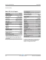
Страница 20: ...products is a Genie policy Product specifications are subject to change without notice SPECIFICATIONS Deutz TD 2 9 L4 Engine Displacement 2925 cm3 Number of cylinders 4 Bore and stroke 3 62 x 4 33 inc...

Страница 21: ...ters Drop Box Lubrication Drop Box 0 26 gallons 1 liters Rear Axle Lubrication Rear differential 6 34 quarts 6 liters Axle planetary end each 1 quart 0 95 liters Oil viscosity requirements Differentia...

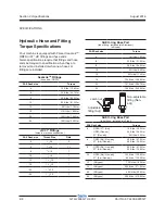
Страница 22: ...1 1 4 8 3 4 16 1 10 7 8 14 1 12 1 1 16 12 1 16 1 5 16 12 1 20 1 5 8 12 1 24 1 7 8 12 1 SAE O ring Boss Port tube fitting installed into Aluminum all types SAE Dash size Torque 4 14 ft lbs 19 Nm 6 23...

Страница 23: ...tings 1 Align the tube flare hex nut against the nose of the fitting body body hex fitting and tighten the hex nut to the body hex fitting to hand tight approximately 30 in lbs 3 4 Nm 2 Make a referen...

Страница 24: ...ZE THREAD i n l bs N m i n l bs N m i n l bs N m i n l bs N m i n l bs N m 20 80 9 100 11 3 110 12 4 140 15 8 130 14 7 28 90 10 1 120 13 5 120 13 5 160 18 140 15 8 ft l bs N m ft l bs N m ft l bs N m...

Страница 25: ...e with the machine in the following configuration Machine parked on a firm level surface Boom in the stowed position Key switch in the off position with the key removed Wheels chocked About This Secti...

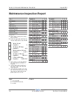
Страница 26: ...ion report to use for each inspection Store completed forms as required Maintenance Schedule There are five types of maintenance inspections that must be performed according to a schedule daily quarte...

Страница 27: ...150 Watertown SD 57201 6150 605 882 4000 Genie UK The Maltings Wharf Road Grantham Lincolnshire NG31 6BH England 44 1476 584333 Copyright 2011 Terex Corporation Genie is a registered trademark of Tere...

Страница 28: ...m service repair and re inspect it After repair place a check in the R box Checklist A Y N R A 1 Manuals and decals A 2 Pre operation inspect A 3 Function tests A 4 Lubricate the boom A 5 Engine maint...

Страница 29: ...d and could result in unsafe operating conditions 1 Check to make sure that the operator s and safety manuals are present and complete in the storage container in the operator s compartment 2 Examine...

Страница 30: ...Inspection also serves to determine if routine maintenance procedures are required Complete information to perform this procedure is available in the appropriate operator s manual Refer to the Operat...

Страница 31: ...n wear pad contact surfaces Proceed to step 2 2 Apply a thin layer of grease to the underside of the number 2 boom tube where it makes contact with the number 1 boom tube lower wear pads 3 Lubricate t...

Страница 32: ...bout 11 8 in 30 cm above the ground Extend the telescope and check if the system enters the alarm mode once reached the distance indicated in the load charts for the attachment fitted to the machine 2...

Страница 33: ...rocedures and additional axle information is available in the Dana Axle S211 Service Manual Dana Axle Service Manual Genie part number 57 4700 0026 CHECKLIST A PROCEDURES A 8 Perform Axle Maintenance...

Страница 34: ...intenance Axle specifications require that this procedure be performed first time after 10 working hours then weekly Axle grease Required maintenance procedures and additional axle information is avai...

Страница 35: ...2 Inspect for a liberal coating of dielectric grease in the following locations All harness connectors 3 Start the engine and raise the boom so there is enough room to access and remove all the covers...

Страница 36: ...t the Tires Wheels and Lug Nut Torque Genie requires that the first inspection be performed after the first 50 hours of operation Genie requires that this procedure be performed every 250 hours or qua...

Страница 37: ...service life Dirty oil may cause the machine to perform poorly and continued use may cause component damage Extremely dirty conditions may require oil changes to be performed more often Refer to Secti...

Страница 38: ...r sides of the profile These pads are secured to both fixed and mobile part of every section 1 Extend the boom until the wear pads are accessible 2 Inspect each pad and ensure that the pad thickness i...

Страница 39: ...enie specifications require that this procedure be performed every 100 250 hours Differential lubricating oil check add Planetary reduction lubricating oil check add Oil breather clean Required mainte...

Страница 40: ...eutz approved oil rated DCQ III or better Lubricating oil filter change Coolant additive concentration check Intake air pipes check for damage V belts check Fuel pre cleaner fuel pre filter clean Requ...

Страница 41: ...essential to safe operation and good machine performance Failure to detect damage to the forks could result in a hazardous operating condition 1 Thoroughly clean the lifting forks 2 Inspect the forks...

Страница 42: ...ge Extremely dirty conditions may require that the filter element be replaced more often CAUTION Bodily injury hazard Beware of hot oil Contact with hot oil may cause severe burns 1 Start the engine 2...

Страница 43: ...00 0026 CHECKLIST D PROCEDURES D 3 Perform Engine Maintenance Engine specifications require that this procedure be performed every 1000 hours Deutz TD 2 9 L4 Charge air cooler entry area drain lube oi...

Страница 44: ...form this procedure with the engine off and the parking brake engaged 1 Open the engine cover 2 Lift up the three clamping yoke 3 Remove the filter hood 4 Pull out the filter element 5 Blow out with d...

Страница 45: ...be performed every year Deutz TD 2 9 L4 Engine monitor warning system Maintenance only to be carried out by authorised service personnel Fuel pre filter replace Required maintenance procedures and ad...

Страница 46: ...ydraulic oil the oil may be tested by an oil distributor for specific levels of contamination to verify that changing the oil is necessary If the hydraulic oil is not replaced at the two year inspecti...

Страница 47: ...he Deutz TD 2 9 L4 Operation and Maintenance Manual Deutz part number 0312 3893 Deutz TD 2 9 L4 Operation and Maintenance Manual Genie part number 57 4700 0006 E 3 Perform Engine Maintenance Engine sp...

Страница 48: ...ne specifications require that this procedure be performed every 6000 hours Deutz TD 2 9 L4 General engine overhaul Required maintenance procedures and additional engine information is available in th...

Страница 49: ...ction Most of the procedures in this section should only be performed by a trained service professional in a suitably equipped workshop Select the appropriate repair procedure after troubleshooting th...

Страница 50: ...ighten How to Remove the Lifting Fork Frame 1 With the boom in the stowed position attach a lifting strap from an overhead crane to the top of the lifting fork frame at the front of the boom Support t...

Страница 51: ...fting cylinder rod side and put some tension on it 7 Using a soft metal drift remove the slave cylinder locking pin from the boom support DANGER Crushing hazard The cylinder will fall if not properly...

Страница 52: ...When removing a hose assembly or fitting the O ring on the fitting and or hose end must be replaced and then torqued to specification during installation Refer to Section 2 Hydraulic Hose and Fitting...

Страница 53: ...and the pad supports d from the first boom section 8 Release the lifting strap to lay the second section b on the first section a 9 Remove the lateral pads e and the top pads f from the first section...

Страница 54: ...t allow oil to squirt or spray NOTICE Component damage hazard Hoses can be damaged if they are kinked or pinched 4 Attach a lifting strap from an overhead crane to the rod end of the lift cylinder Sup...

Страница 55: ...pes from the cylinder shutoff valve Cap the cylinder fittings WARNING Bodily injury hazard Spraying hydraulic oil can penetrate and burn skin Loosen hydraulic connections very slowly to allow the oil...

Страница 56: ...under the hydraulic hoses before disconnecting 5 Tag disconnect and plug the hydraulic hoses from the level cylinder Cap the cylinder fittings WARNING Bodily injury hazard Spraying hydraulic oil can p...

Страница 57: ...pport the cylinder 6 Remove the protective guard a of the shut off valve 7 Place a container of suitable size under the hydraulic hoses before disconnecting 8 Tag disconnect and plug the hydraulic hos...

Страница 58: ...Start the engine 2 Raise the boom to a horizontal position 3 Retract the boom 4 Turn the machine off and remove the key from the key switch 5 Before replacing a hydraulic hose thoroughly clean the ma...

Страница 59: ...slowly to allow the oil pressure to dissipate gradually Do not allow oil to squirt or spray e 12 Pull hoses e outward until it comes out completely 13 Remove the rope from the old hydraulic hoses and...

Страница 60: ...r service is required 1 Start the diesel engine and raise the boom above the cab 2 Get behind the front right wheel and disconnect the battery from the machine WARNING Electrocution burn hazard Contac...

Страница 61: ...in and an overhead crane slowly raise the cabin away from the machine and set it on a supporting device NOTICE Component damage hazard Wrapping a strap around the cab and lifting using an overhead cra...

Страница 62: ...Remove the nut securing the steering wheel to the column and remove the steering wheel 2 2 Machine Controls How to Remove the Steering Column 1 Get behind the front right wheel and disconnect the batt...

Страница 63: ...olumn 2 Working under the dashboard locate the hydraulic hoses of the steer rotation actuator 3 Tag disconnect and cap the hydraulic hoses and steer rotation actuator holes WARNING Bodily injury hazar...

Страница 64: ...Pedal Assembly 1 Remove the front dashboard lower part 2 Get behind the front right wheel and disconnect the battery from the machine WARNING Electrocution burn hazard Contact with electrically charge...

Страница 65: ...battery from the machine WARNING Electrocution burn hazard Contact with electrically charged circuits could result in death or serious injury Remove all rings watches and other jewelry 2 Act on the l...

Страница 66: ...l and disconnect the battery from the machine WARNING Electrocution burn hazard Contact with electrically charged circuits could result in death or serious injury Remove all rings watches and other je...

Страница 67: ...e hydraulic tank Refer to Section 2 Specifications 6 Remove the drain plug from the hydraulic tank and completely drain the tank CAUTION Bodily injury hazard Beware of hot oil Contact with hot oil may...

Страница 68: ...time a colored warning lamp is illuminated and the fault code is shown on the engine diagnostic display located on the dashboard in the operator s compartment To learn the specifications of and how to...

Страница 69: ...parking brake 5 Select two wheel steer mode 6 Set the transmission lever in the neutral position 7 Raise the front wheels of the machine WARNING Tow the machine for short distances and at a low speed...

Страница 70: ...negative brakes 1 On both sides unscrew the nuts 5 approximately 10 mm nearby the bolt head 2 Screw in the brake release bolts 6a and 6b The screw must be tightened 1 4 turn at a time in sequence unti...

Страница 71: ...ly to allow the oil pressure to dissipate gradually Do not allow oil to squirt or spray 4 Loosen the lug nuts of both wheels on the axle to be removed Do not remove the lug nuts 5 Raise the end of the...

Страница 72: ...ushing the throttle pedal Result the pressure gauge reads 4060 psi 280 bar The pump is good Pressure is not within specification The pump needs to be adjusted OR the pump or pump coupling is faulty an...

Страница 73: ...d result in death or serious injury Remove all rings watches and other jewelry 3 Remove the cover that is under engine 4 Tag disconnect and plug the hoses located at the right side of the pump Cap the...

Страница 74: ...tingTorqueSpecifications Note Perform this procedure with the engine off and cool to the touch 1 Open the engine cover 2 Remove the cover that is under engine 3 Install the boom function pump on the e...

Страница 75: ...YDRAULIC PUMPS How to Prime the Boom and Steering Function Pump 1 Start the engine allow the engine to run at low idle for 15 seconds then shut off the engine 2 Wait 15 seconds then start the engine a...

Страница 76: ...re gauge to port TP3 hydrostatic transmission boost pressure test port 3 Start the engine Result the pressure gauge connected to test port TP3 reads 360 psi 25 bar Pressure is not within specification...

Страница 77: ...nd disconnect the battery from the machine WARNING Electrocution burn hazard Contact with electrically charged circuits could result in death or serious injury Remove all rings watches and other jewel...

Страница 78: ...and cool to the touch 1 Open the engine compartment 2 Remove the cover that is under engine 3 Place a suitable support for the pump to install it from the bottom 4 Install the hydrostatic transmissio...

Страница 79: ...est port 2 Start the engine Run at low idle for 5 seconds Shut the engine off and wait for 15 seconds 3 Start the engine Run at low idle for 10 seconds Shut the engine off and wait for 15 seconds 4 No...

Страница 80: ...and steering functions hydraulic test port 2 Start the engine 3 Increase the engine speed to maximum rpm 4 Fully extend the boom without releasing the joystick Result the pressure gauge reads 1450 psi...

Страница 81: ...ected to port TP1 reads 310 bar 6 Tilt the forks up or down Result the pressure gauge reads 4350 psi 300 bar The pressure setting is correct Pressure is not within specification Adjust the fork tilt r...

Страница 82: ...e Perform this procedure with the engine off and cool to the touch 1 Close the hydraulic tank ball valve 2 Screw a lifting eye bolt into the threaded hole which is located on the function manifold 3 T...

Страница 83: ...0 to 350 bar pressure gauge to port TP1 boom and steering functions hydraulic circuit test port 2 Start the engine 3 Increase the engine speed to maximum rpm 4 Moving the joystick retract the boom Res...

Страница 84: ...t Hydraulic proportional control A3 B3 b Auxiliary Circuit Hydraulic proportional control A4 B4 c Fork tilt Hydraulic proportional control A2 B2 d Boom up down Hydraulic proportional control A1 B1 e L...

Страница 85: ...or serious injury Remove all rings watches and other jewelry Note If the machine has been in operation allow the coil to cool at least 3 hours before performing this test 1 Tag and disconnect the wiri...

Страница 86: ...The battery should read 9V DC or more when measured across the terminals 3 Set a multimeter to read DC current Note The multimeter when set to read DC current should be capable of reading up to 800 m...

Страница 87: ...0 should be easy to tight the screws by hands to improve the tightening force applied by the screws and to prevent any loosening we recommend to use Loctite 242 3 The tightening operation of the 2 M10...

Страница 88: ...tion 4 Repair Procedures 3 It means that the axle must see high shocks before calibration 4 We suggest driving fast 10 times on a beam fixed to the ground 5 After this operation it is recommended to l...

Страница 89: ...Valve How to Test the Parking Brake Reducing Valve 1 Connect a 0 to 870 psi 0 to 60 bar pressure gauge to test port TP5 2 Start the engine and let it run at low idle 3 Engage the parking brake Result...

Страница 90: ...4 42 GTH 2506 GTH 3007 Part No 57 4400 9220GT August 2018 Section 4 Repair Procedures This page intentionally left blank 1RYHPEHU 7 7 7 7 7 7 3DUW 1R LY 7KLV SDJH LQWHQWLRQDOO OHIW EODQN...

Страница 91: ...ied perform each repair procedure with the machine in the following configuration Machine parked on a firm level surface Boom in the stowed position Key switch in the off position with the key removed...

Страница 92: ...Install the forks load a weight of 5500 lbs 2500 kg bring the forks as close as possible to the ground and start extending the boom slowly to discharge the weight from the rear axle the rear wheels w...

Страница 93: ...structions in the appropriate operator s manual on your machine Be sure that all necessary tools and test equipment are available and ready for use Be aware of the following hazards and follow general...

Страница 94: ...tive fault codes page press the diagnostic button d and hold it pressed for at least 5 seconds Active Codes vs Stored Codes Active fault codes indicating an engine condition or conditions which have n...

Страница 95: ...Not enough oxygen for regeneration 523911 0 Burner dosing valve DV2 overcurrent at the end of the injection phase 523911 12 Burner dosing valve DV2 powerstage over temperature 523911 3 Burner dosing v...

Страница 96: ...ed 523934 0 Fuel Balance Control integrator injector 6 in firing order maximum value exceeded 523929 1 Fuel Balance Control integrator injector 1 in firing order minimum value exceeded 523930 1 Fuel B...

Страница 97: ...SCR system downstream cat DPF system downstream cat 523943 9 Timeout Error PCK2PCK for CAN Receive Frame AT1OGCVol2 information factors Sensorcalibration for NOX Sensor SCR system downstream cat DPF...

Страница 98: ...warning threshold Overrun Mode 108 3 Sensor error ambient air pressure signal range check high 108 4 Sensor error ambient air pressure signal range check low 171 3 Sensor error environment temperatur...

Страница 99: ...ing valve DV1 short circuit to battery high side 523915 4 HCI dosing valve DV1 short circuit to ground 523915 11 HCI dosing valve DV1 short circuit high side powerstage 523916 2 Sensor HCI dosing valv...

Страница 100: ...ct 651 5 Injector 1 in firing order interruption of electric connection 652 5 Injector 2 in firing order interruption of electric connection 653 5 Injector 3 in firing order interruption of electric c...

Страница 101: ...12 Internal ECU monitoring detection reported error 523612 12 Internal ECU monitoring detection reported error 523612 12 Internal ECU monitoring detection reported error 523612 12 Internal ECU monito...

Страница 102: ...rpump pressure signal range check high 523919 4 Sensor error airpump pressure signal range check low 523920 2 Sensor exhaustgas back pressure plausibility error 523920 0 Physical range check high for...

Страница 103: ...2 Multiple Stage Switch engine speed control parameter plausibility error 523452 3 Multiple Stage Switch engine torque limitation curve short circuit to battery 523452 4 Multiple Stage Switch engine...

Страница 104: ...ror normal condition 523720 2 Sensor urea supply module heater temperature plausibility error cold start condition 523721 2 Sesnor urea supply module temperature plausibility error normal condition 52...

Страница 105: ...ay high side short circuit to ground 677 5 Starter relay no load error 677 12 Starter relay powerstage over temperature 677 3 Starter relay low side short circuit to battery 677 4 Starter relay low si...

Страница 106: ...ground 51 12 Mechanical actuator defect EGR Valve 2 9 3 6 or Throttle Valve 6 1 7 8 51 6 Actuator error EGR Valve 2 9 3 6 or Throttle Valve 6 1 7 8 signal range check high 51 5 Actuator error EGR Valv...

Страница 107: ...to battery 4366 5 SCR main relay secondary side shortcut to ground 4341 5 SCR heater relay urea supplyline secondary side open load 523719 5 SCR heater relay urea supply modul secondary side open loa...

Страница 108: ...ature maximum exceeded 3031 1 DEF Tank temperature below minimum 3031 3 Sensor error urea tank temperature short circuit to battery 3031 4 Sensor error urea tank temperature short circuit to ground 97...

Страница 109: ...r 523914 11 Glow plug control internal error 524018 14 DPF wasn t regenerated power reduction phase 1 manuell regeneration request 524022 14 DPF wasn t regenerated power reduction phase 2 manuell rege...

Страница 110: ...ug control unit SPCU electrical fault 524017 12 Spark plug control unit SPCU internal error 523989 0 Fuel Balance Control integrator injector 7 in firing order maximum value exceeded 523990 0 Fuel Bal...

Страница 111: ...order interruption of electric connection 524000 3 Injector 7 in firing order short circuit 524001 3 Injector 8 in firing order short circuit 524000 4 High side to low side short circuit in the inject...

Страница 112: ...ticulate filter downstream warning 3248 1 Physical range check low for exhaust gas temperature particulate filter downstream 3248 1 Physikal range check low for exhaust gas temperature particulate fil...

Страница 113: ...arning threshold exceeded 523960 1 High exhaust gas temperature EGR cooler downstream shut off threshold exceeded 1180 0 Turbocharger Wastegate CAN feedback warning threshold exceeded 1180 1 Turbochar...

Страница 114: ...Frame A1DOC 524115 9 Timeout error of CAN Transmit Frame AT1S 524116 9 Timeout error of CAN Transmit Frame SCR2 524117 9 Timeout error of CAN Transmit Frame SCR3 524097 9 Timeout error of CAN Transmi...

Страница 115: ...check high 51 6 Actuator error EGR Valve 2 9 3 6 or Throttle Valve 6 1 7 8 signal range check high 51 6 Actuator EGR Valve 2 9 3 6 or Throttle Valve 6 1 7 8 over current 51 6 Actuator error EGR Valve...

Страница 116: ...high 105 4 Sensor error charged air temperature signal range check low 107 0 High air filter differential pressure warning threshold exceeded 107 3 Sensor error airfilter differential pressure short...

Страница 117: ...High low fuel temperature warning threshold exceeded 174 0 High Low fuel temperature shut off threshold exceeded 175 0 Physical range check high for oil temperature 175 0 High oil temperature warning...

Страница 118: ...S lamp open load 624 12 SVS lamp powerstage over temperature 630 12 Access error EEPROM memory delete 630 12 Access error EEPROM memory read 630 12 Access error EEPROM memory write 639 14 CAN Bus 0 Bu...

Страница 119: ...lamp powerstage over temperature 729 5 Cold start aid relay open load 729 12 Cold start aid relay over temperature error 898 9 Timeout Error of CAN Receive Frame TSC1TE Setpoint 975 3 Digital fan cont...

Страница 120: ...tegate actuator EOL calibration not performed correctly 1188 11 Wastegate actuator over temperature 145 C 1188 11 Wastegate actuator over temperature 135 C 1188 11 Wastegate actuator operating voltage...

Страница 121: ...Receive Frame AT1IG1Vol NOX Sensor SCR system upstream cat DPF system downstream cat length of frame incorrect 3224 9 Timeout Error of CAN Receive Frame AT1IG1 NOX sensor upstream 3224 9 Timeout Erro...

Страница 122: ...or error urea tank level signal range check low 3699 2 DPF differential pressure sensor and a further sensor or actuator CRT system defective 3699 2 Temperature sensor us and ds DOC simultaneously def...

Страница 123: ...relay secondary side open load 4366 5 SCR main relay secondary side Shortcut to battery 4366 5 SCR main relay secondary side shortcut to ground 4366 5 SCR Tank heating valve secundary side open load...

Страница 124: ...ne Protection 523216 9 Timeout Error of CAN Receive Frame PrHtEnCmd pre heat command engine command 523240 9 Timeout CAN message FunModCtl Function Mode Control 523330 14 Immobilizer status fuel block...

Страница 125: ...oring detection reported error 523612 12 Internal ECU monitoring detection reported error 523612 12 Internal ECU monitoring detection reported error 523612 12 Internal ECU monitoring detection reporte...

Страница 126: ...32 2 Metering control is not performed in time error 523632 16 Pump pressure SCR metering unit too high 523632 18 Pump pressure SCR metering unit too low 523633 11 Nox conversion rate insufficient SCR...

Страница 127: ...23769 9 Timeout Error of CAN Receive Frame Passive TSC1AR 523770 9 Timeout Error of CAN Receive Frame Passive TSC1DE 523776 9 Timeout Error of CAN Receive Frame TSC1TE active 523777 9 Passive Timeout...

Страница 128: ...high for burner dosing valve DV2 downstream pressure shut off regeneration 523912 1 Physical range check low for burner dosing valve DV2 downstream pressure shut off regeneration When burner injector...

Страница 129: ...k high for DV1 DV2 upstream temperature shut off regeneration 523918 1 Physical range check low for DV1 DV2 upstream temperature shut off regeneration 523918 2 Sensor DV1 DV2 upstream temperature plau...

Страница 130: ...ector 3 in firing order minimum value exceeded 523932 0 Fuel Balance Control integrator injector 4 in firing order maximum value exceeded 523932 1 Fuel Balance Control integrator injector 4 in firing...

Страница 131: ...23950 1 Zerofuel calibration injector 5 in firing order minimum value exceeded 523951 0 Zerofuel calibration injector 6 in firing order maximum value exceeded 523951 1 Zerofuel calibration injector 6...

Страница 132: ...ort circuit in the injector 8 in firing order 524001 5 Injector 8 in firing order interruption of electric connection 524004 12 Too many recognized misfires in cylinder 7 in firing order 524005 12 Too...

Страница 133: ...4038 9 Timeout error of CAN Receive Frame ComMS_Sys1TO error memory Slave Master Slave internal CAN message 524039 9 Timeout error of CAN Receive Frame ComMS_Sys2TO error memory Slave Master Slave int...

Страница 134: ...Frame ComRxDPFCtl 524105 9 Timeout error of CAN Transmit Frame ComEGRMsFlw 524106 9 Timeout error of CAN Receive Frame ComRxEGRMsFlw1 524107 9 Timeout error of CAN Receive Frame ComRxEGRMsFlw2 524108...

Страница 135: ...ure that all necessary tools and test equipment are available and ready for use About This Section There are two groups of schematics in this section Electrical Schematics WARNING Electrocution burn h...

Страница 136: ...lve Flow regulator Relief valve 3 position 4 way proportional directional valve 2 position 3 way directional valve 3 position 4 way solenoid valve 2 position 4 way solenoid valve 2 position 2 way sole...

Страница 137: ...August 2018 Part No 57 4400 9220GT GTH 2506 GTH 3007 7 3 Section 7 Schematics Electrical Schematic Sheet 1 of 16 GTH 2506 From GTH250619M 1001 GTH300719M 501...

Страница 138: ...7 4 GTH 2506 GTH 3007 Part No 57 4400 9220GT August 2018 Section 7 Schematics ELECTRICAL SCHEMATIC 1 D 7HUH EUDQG 1 1 1 530 KRXU Sheet 2 of 16 GTH 2506 From GTH250619M 1001 GTH300719M 501...

Страница 139: ...August 2018 Part No 57 4400 9220GT GTH 2506 GTH 3007 7 5 Section 7 Schematics ELECTRICAL SCHEMATIC Sheet 3 of 16 GTH 2506 From GTH250619M 1001 GTH300719M 501...

Страница 140: ...7 6 GTH 2506 GTH 3007 Part No 57 4400 9220GT August 2018 Section 7 Schematics ELECTRICAL SCHEMATIC Sheet 4 of 16 GTH 2506 From GTH250619M 1001 GTH300719M 501...

Страница 141: ...August 2018 Part No 57 4400 9220GT GTH 2506 GTH 3007 7 7 Section 7 Schematics ELECTRICAL SCHEMATIC Sheet 5 of 16 GTH 2506 From GTH250619M 1001 GTH300719M 501...

Страница 142: ...7 8 GTH 2506 GTH 3007 Part No 57 4400 9220GT August 2018 Section 7 Schematics ELECTRICAL SCHEMATIC Sheet 6 of 16 GTH 2506 From GTH250619M 1001 GTH300719M 501...

Страница 143: ...August 2018 Part No 57 4400 9220GT GTH 2506 GTH 3007 7 9 Section 7 Schematics ELECTRICAL SCHEMATIC Sheet 7 of 16 GTH 2506 From GTH250619M 1001 GTH300719M 501...

Страница 144: ...7 10 GTH 2506 GTH 3007 Part No 57 4400 9220GT August 2018 Section 7 Schematics ELECTRICAL SCHEMATIC Sheet 8 of 16 GTH 2506 From GTH250619M 1001 GTH300719M 501...

Страница 145: ...August 2018 Part No 57 4400 9220GT GTH 2506 GTH 3007 7 11 Section 7 Schematics ELECTRICAL SCHEMATIC Sheet 9 of 16 GTH 2506 From GTH250619M 1001 GTH300719M 501...

Страница 146: ...7 12 GTH 2506 GTH 3007 Part No 57 4400 9220GT August 2018 Section 7 Schematics ELECTRICAL SCHEMATIC Sheet 10 of 16 GTH 2506 From GTH250619M 1001 GTH300719M 501...

Страница 147: ...August 2018 Part No 57 4400 9220GT GTH 2506 GTH 3007 7 13 Section 7 Schematics ELECTRICAL SCHEMATIC Sheet 11 of 16 GTH 2506 From GTH250619M 1001 GTH300719M 501...

Страница 148: ...7 14 GTH 2506 GTH 3007 Part No 57 4400 9220GT August 2018 Section 7 Schematics ELECTRICAL SCHEMATIC Sheet 12 of 16 GTH 2506 From GTH250619M 1001 GTH300719M 501...

Страница 149: ...August 2018 Part No 57 4400 9220GT GTH 2506 GTH 3007 7 15 Section 7 Schematics ELECTRICAL SCHEMATIC Sheet 13 of 16 GTH 2506 From GTH250619M 1001 GTH300719M 501...

Страница 150: ...7 16 GTH 2506 GTH 3007 Part No 57 4400 9220GT August 2018 Section 7 Schematics ELECTRICAL SCHEMATIC Sheet 14 of 16 GTH 2506 From GTH250619M 1001 GTH300719M 501 86...

Страница 151: ...August 2018 Part No 57 4400 9220GT GTH 2506 GTH 3007 7 17 Section 7 Schematics ELECTRICAL SCHEMATIC Sheet 15 of 16 GTH 2506 From GTH250619M 1001 GTH300719M 501 1 D 7HUH EUDQG 1 1 1 530 KRXU 6 6 6...

Страница 152: ...7 18 GTH 2506 GTH 3007 Part No 57 4400 9220GT August 2018 Section 7 Schematics ELECTRICAL SCHEMATIC Sheet 16 of 16 GTH 2506 From GTH250619M 1001 GTH300719M 501...

Страница 153: ...August 2018 Section 7 Schematics 1RYHPEHU 7 7 7 7 7 7 3DUW 1R LY 7KLV SDJH LQWHQWLRQDOO OHIW EODQN 7 19 7 20 Hydraulic Schematic...

Страница 154: ...enter safety valve piloting ratio 4 2 1 cracking pressure 350 bar Single overcenter safety valve piloting ratio 4 2 1 cracking pressure 350 bar Single overcenter safety valve piloting ratio 4 2 1 crac...

Страница 155: ...ng ratio 4 2 1 cracking pressure 350 bar Single overcenter safety valve piloting ratio 4 2 1 cracking pressure 350 bar Single overcenter safety valve piloting ratio 4 2 1 cracking pressure 350 bar Cra...

Отзывы: