Service and Repair Manual
May 2022
Ground Controls
58
GS
™
-2669 RT • GS
™
-3369 RT • GS
™
-4069 RT
Part No. 1306516GT
8-5
Level Sensor - Models with
Outriggers
The Electronic Control Module (ECM) is
programmed to deactivate the lift and drive
functions and activate an alarm when a signal is
received from the level sensor.
When the outriggers are stowed, the tilt alarm
sounds when the incline of the chassis exceeds 2°
to the side.
When the outriggers are deployed, the tilt alarm
sounds when the incline of the chassis exceeds
0.8° to the side.
At all times, the tilt alarm sounds when the incline
of the chassis exceeds 3° to the front or rear.
How to Install and Calibrate the
Level Sensor
Tip-over hazard. Failure to install
or calibrate the level sensor as
instructed will compromise
machine stability and cause the
machine to tip over, resulting in
death or serious injury. Do not
install or calibrate the level
sensor other than specified in
this procedure.
Note: Perform this procedure with the machine on
a firm, level surface and the platform in the stowed
position. Use a digital level to confirm.
1 Remove the platform controls from the
platform.
If you are not installing a new level sensor,
proceed to step 7.
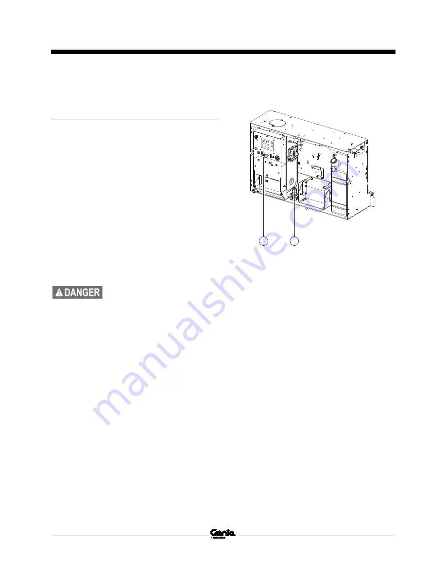
2 Locate the level sensor in the ground controls
compartment.
1 ground control box
2 level sensor
3 Tag and disconnect the wire harness from the
level sensor.
4 Remove the retaining fasteners securing the
level sensor to the compartment. Remove the
level sensor from the machine.
1
2
Содержание GS-2669 IC
Страница 79: ...May 2022 Service and Repair Manual Manifolds Part No 1306516GT GS 2669 RT GS 3369 RT GS 4069 RT 65...
Страница 87: ...May 2022 Service and Repair Manual Manifolds Part No 1306516GT GS 2669 RT GS 3369 RT GS 4069 RT 73...
Страница 89: ...May 2022 Service and Repair Manual Manifolds Part No 1306516GT GS 2669 RT GS 3369 RT GS 4069 RT 75...
Страница 141: ...May 2022 Service and Repair Manual 127 GM 998L Engine Wire Harness...
Страница 142: ...Service and Repair Manual May 2022 128 GS 2669 RT GS 3369 RT GS 4069 RT Part No 1306516GT GM 998L Engine Wire Harness...
Страница 144: ...Service and Repair Manual May 2022 130 Control Panel Circuit Diagram...
Страница 145: ...May 2022 Service and Repair Manual 131 Electrical Schematic GS 69 RT GM 998L Models ANSI CSA...
Страница 148: ...Service and Repair Manual May 2022 134 Electrical Schematic GS 69 RT GM 998L Models ANSI CSA...
Страница 149: ...May 2022 Service and Repair Manual 135 Electrical Schematic GS 69 RT GM 998L Models ANSI CSA...
Страница 152: ...Service and Repair Manual May 2022 138 Electrical Schematic GS 69 RT Diesel Models ANSI CSA...
Страница 153: ...May 2022 Service and Repair Manual 139 Electrical Schematic GS 69 RT Diesel Models ANSI CSA...
Страница 156: ...Service and Repair Manual May 2022 142 Electrical Schematic GS 69 RT Diesel Models ANSI CSA...
Страница 157: ...May 2022 Service and Repair Manual 143 Electrical Schematic GS 69 RT GM 998L Models AS CE...
Страница 160: ...Service and Repair Manual May 2022 146 Electrical Schematic GS 69 RT GM 998L Models AS CE...
Страница 161: ...May 2022 Service and Repair Manual 147 Electrical Schematic GS 69 RT GM 998L Models AS CE...
Страница 164: ...Service and Repair Manual May 2022 150 Electrical Schematic GS 69 RT Diesel Models AS CE...
Страница 165: ...May 2022 Service and Repair Manual 151 Electrical Schematic GS 69 RT Diesel Models AS CE...
Страница 168: ...Service and Repair Manual May 2022 154 Electrical Schematic GS 69 RT Diesel Models AS CE...
Страница 169: ...May 2022 Service and Repair Manual 155 Hydraulic Schematic GS 69 RT...
Страница 171: ......


