74
STEERING STEM AND FRONT SUSPENSION
REMOVAL AND DISASSEMBLY
(
Refer to preceding page
)
□
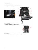
remove the handle cover
(
refer to preceding page
)
□
remove under decorating cover
(
refer to the preceding page
)
□
remove legshield
(
refer to preceding page
)
□
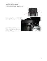
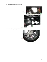
remove front wheel
(
refer to preceding page
)
□
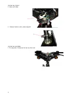
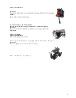
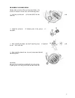
disconnect the front and rear brake light switch
lead wires .
□
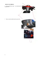
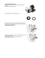
Remove the rear brake cable .
□
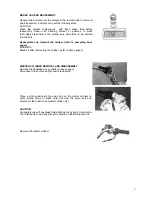
Remove throttle grip case .
□
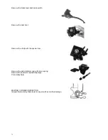
Remove throttle cable .
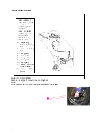
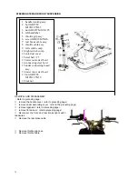
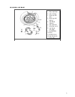
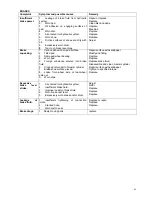
1.
handle jointing assy.
2.
bolt GB5789
M10X1.25X45
3.
nut GB6187 M10X1.25
4.
left handlebar
5.
throttle grip assy.
6.
screw GB818 M5X10
7.
rear brake cable assy.
8.
throttle cable assy.
9.
left switch comp.
10.
right switch comp.
11.
anti-dust cover
12.
steel ball
¢
5
13.
lower outer steel bowl
14.
connecting steel bowl
15.
under connecting borad
assy.
16.
lower inner steel bowl
17.
bolt GB5789
M10X1.25X30
18.
locknut
①
③
④
②
Содержание XOR 125
Страница 6: ...5...
Страница 20: ...19 14...
Страница 43: ...42 CHAPTER 4 FUEL AND LUBRICATION SYSTEM CONTENTS FUEL SWITCH CARBURETOR...
Страница 64: ...63 3 Disconnect throttle cable and oil pump cable 4 Remove rear brake cable adjusting nut...
Страница 91: ...90 WIRE CABLE AND BRAKE HOSE ROUTING...
Страница 92: ...91 carburetor...
Страница 93: ...92...
Страница 94: ...93 Ignition coil Starting relay CDI HORN POWER SWITCHH...
Страница 96: ...95...

