FORM NO. 747-23 Rev. B (FILE 12549)
Litho in U.S.A.
8
ELECTRICAL
NOTE: The humidifier has a built-in "Humidity Control" which is an adjustable
thermostat that completes the humidifier motor circuit on rising duct
temperature. The thermostat senses the peaks and valleys of the modulating
duct temperature caused by the furnace heating cycle. When the control is set
on "HIGH", the humidifier will operate a greater percentage of the furnace
cycle; and when set on "LOW", it will operate a lesser percentage of the cycle.
A wall or duct mounted humidistat becomes an optional accessory with the
built-in "Humidity Control".
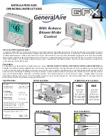
WIRING 24 VOLT MODEL HUMIDISTAT OPTIONAL
The humidifier does not require connection to the furnace blower circuit.
Connect the wire supplied to the two wires on the humidifier. Slide the plastic
tubing over the terminals. Connect the two wires to the transformer and plug
transformer into a 115 volt electrical outlet that will remain on at all times. Do
not use an extension cord. If a humidistat is used in conjunction with the built-
in "Humidity Control", connect the humidistat in series with the humidifier as
shown and turn the "Humidity Control" to the "ON" position. ALL WIRING
SHOULD COMPLY WITH LOCAL ELECTRICAL CODES.
TEST RUN HUMIDIFIER
Turn on the water supply and electrical power. Set the "Humidity Control" to the "ON" position. The humidifier motor should turn the drum at 1
RPM. The float valve should maintain a water level of approximately 1-1/2 inches. The "OFF" position on the "Humidity Control" corresponds to a
trunk duct temperature of 160ºF. and the "ON" position to a temperature of 70ºF. With the control set on "MED" (115ºF.), the humidifier will run
approximately 50% of the available furnace operating time. Initially the "Humidity Control" may be left on "MED" with instructions to the user to
adjust higher or lower as required.
The mid-range set point for warm air heating systems employing heat pumps will be in the "HIGH" range because of the lower trunk duct
temperatures. A humidistat may be required on heat pump systems.
INSTALLER: Please instruct user on the importance of frequent draining through the quick-drain device to keep water fresh and reduce the
mineral concentration in the water pan.
21
22
1
2
3
5
6
9
10
11
12
13
14
15
16
17
18
4
7 8
19
20
27
26
23
24
25
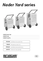
PARTS LIST FOR HUMIDIFIER
FILL OUT AND MAIL THIS
WARRANTY CARD AND
LITERATURE REQUEST FORM
A
IR
C
LEANERS AND
A
IR
P
URIFIERS
H
UMIDIFIERS
D
IGITAL
H
UMIDITY
G
AGE
A
IR
F
ILTER
G
AGE
F
UEL
O
IL
F
ILTERS AND
A
CCESSORIES
1. 727-7 DRUM SHAFT
2. P-188 RETAINER CLIP
3. 727-5 DRUM END (2 REQ'D)
4. 727-4 DRUM ASSEMBLY
5. 727-12 EVAP. SLEEVE
6. 747-28 MOTOR ASSY.
7. P187 COMPRESSION UNION
8. 747-35 "L" TUBE ASSY.
9. 975-3 ORIFICE NUT
10. 747-11 VALVE WASHER
11. 727-8 SPLASH GUARD
12. 975-6 SHIELD - VALVE
13. 727-24 FITTING - ORIFICE
14. 975-1 VALVE SEAT
15. P118 COTTER PIN
16. 727-34 ARM - FLOAT
17. 727-32 FLOAT BLOCK
18. 747-29 FLOAT VALVE ASSY.
19. 747-7 MOUNTING FRAME
20. 747-30 WINDOW
21. 45-1 DRUM BEARING
22. 747-1 WATER PAN
23. 1099-9 THUMB NUT
24. 747-26 HUMIDITY CONTROL
25. 747-21 NAME PLATE
26. 747-5 QUICK DRAIN
27. P185 CLAMP
PARTS NOT SHOWN:
800UST SADDLE VALVE
727-48 LEAD WIRE ASSY.
747-36 TRANSFORMER
747-9 MOUNTING TEMPLATE
747-38 WATER SUPPLY TUBE KIT
Содержание 747-L
Страница 5: ......