background image

(3) Touch the test leads to any two points of the circuit. The resistance

between those two points will be displayed. If the resistance is
<40

Ω

, the beeper will sound continuously. If there is no continuity

(an open circuit or a resistance >40

Ω

) between the two points, 

OL.

will appear on the readout.

CHECKING THE INTEGRITY OF A DIODE

••

Warning

••

To avoid possible damage to the meter or other equipment, turn off the
power source and discharge all high-voltage capacitors.

(1) Turn the function switch to the 

(2k

Ω

) position.

(2) Plug the black test lead into the front-panel 

COM

jack and the red

test lead into the 

jack.

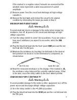
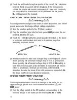
(3) Touch the red test lead to the anode (positive terminal) of the diode

to be tested and the black test lead to its cathode (negative
terminal), as shown below.

(4) Read the diode’s forward bias voltage drop on the display. A silicon

diode typically has a forward voltage drop of 0.7V. A germanium
diode typically has a forward voltage drop of 0.3V. A 

0V

reading in

both directions indicates a shorted diode. A readout of .OL means
either of two things: the leads are reversed, or the diode is
defective. Reverse the leads. If this still produces a readout of 

.OL

,

the diode is defective and should be replaced.

CHECKING BATTERY VOLTAGE

••

Warning

••

To avoid possible electrical shock or damage to the meter, do not
apply a voltage greater than 250V between the meter’s 

and 

COM

jacks.

(1) Turn the rotary switch to the 

position corresponding to the

nominal voltage of the battery to be tested (

12V

9V

or 

1.5V

).

10

RED TEST LEAD

BLACK TEST LEAD

Содержание DMM30

Страница 1: ...8 FUNCTION DIGITAL MULTIMETER WITH NCV DETECTION USER S MANUAL DMM30 Please read this manual carefully and thoroughly before using this product...

Страница 2: ...ions 7 11 General Instructions 7 Holding Readings 7 Measuring AC or DC Voltage 7 8 Measuring DC Current 8 9 Measuring Resistance 9 Checking for Continuity 9 10 Checking the Integrity of a Diode 10 Che...

Страница 3: ...eads A 9V battery is pre installed in a compartment in the back of the unit PRODUCT OVERVIEW Fig 1 shows the labels and positions of the controls LCD and physical structures of the DMM30 Fig 2 shows a...

Страница 4: ...d insulation or exposed metal Check the test leads for continuity Replace damaged test leads before using the meter Verify the meter s operation by measuring a known voltage Do not use the meter if it...

Страница 5: ...esistance continuity diodes or capacitance For all DC functions in both auto and manual ranging mode to avoid the risk of shock due to possible improper reading verify the presence of any AC voltages...

Страница 6: ...n risk of electric Risk of danger Important shock Hazardous information Refer to the voltage manual Low battery indication when shown Earth ground on LCD Diode Continuity Beeper AC or DC Resistance CA...

Страница 7: ...Phillips head screw OPERATING INSTRUCTIONS GENERAL INSTRUCTIONS All parameters are measured through the included test leads Unless you are measuring DC currents larger than 200 mA plug the red test l...

Страница 8: ...A through the 10A jack for more than 10 seconds at a time or for more than 30 seconds every 15 minutes pause 1 minute after each measurement of such a large current 1 Remove power from the circuit to...

Страница 9: ...unsure how much resistance you expect to encounter select the 200 position 2 Plug the black test lead into the front panel COM jack and the red test lead into the jack 3 Measure the resistance by touc...

Страница 10: ...the diode to be tested and the black test lead to its cathode negative terminal as shown below 4 Read the diode s forward bias voltage drop on the display A silicon diode typically has a forward volt...

Страница 11: ...t is carrying at least 110VACRMS The NCV detector works with the rotary function switch in any position SPECIFICATIONS Parameter or Feature Function Attribute Specification AC voltage Measurement rang...

Страница 12: ...tage protection 250VDC ACRMS Fuse protection 250mA 250V fuse for jack 10A 250V fuse for 10A jack Sampling time 3X sec Display No of digits 3 1 2 Maximum count 2000 Low battery indication threshold 6 7...

Страница 13: ...0V fuse Each fuse is located directly behind the jack it protects 7 Using another multimeter or a continuity checker verify that the suspected blown fuse produces a resistance reading consistent with...

Страница 14: ...not apply to damages that General determines to be from an attempted repair by non authorized personnel or misuse alterations normal wear and tear or accidental damage The defective unit must be retur...

Страница 15: ...ntact our Customer Service to obtain an RGA Return Goods Authorization number before forwarding the unit via prepaid freight to the attention of our Service Center at this address General Tools Instru...

Страница 16: ...431 6499 TOLL FREE 800 697 8665 e mail sales generaltools com www generaltools com DMM30 User s Manual Specifications subject to change without notice NOTICE NOT RESPONSIBLE FOR TYPOGRAPHICAL ERRORS...

Отзывы: