PeakTech 1080, Operation Manual
The Acer 1080 Quick Manual is a comprehensive user guide designed to assist users in understanding and maximizing the features of their Acer 1080 device. With step-by-step instructions and detailed illustrations, this manual is available for free download at manualshive.com, ensuring easy access to essential information for your Acer 1080.
Share
Download


Reviews:
No comments
Related manuals for 1080

2015
Brand: Keithley Pages: 158

DM6410
Brand: Sperry instruments Pages: 6

M110A
Brand: UEi Pages: 5

M-1008K
Brand: Elenco Electronics Pages: 20

81 83 50
Brand: Wetekom Pages: 50

CDM45C
Brand: Clarke Pages: 16

ND 2350-1
Brand: IDEAL Pages: 10

ACD-10 PLUS
Brand: Amprobe Pages: 116

ACD-14 PLUS
Brand: Amprobe Pages: 148
1017895
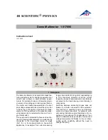
Brand: 3B SCIENTIFIC PHYSICS Pages: 8

3385
Brand: PeakTech Pages: 34

35632-Series
Brand: Oakton Pages: 35

H-7095
Brand: U-Line Pages: 39

17-20AQ-347
Brand: Navair Pages: 23

ND-5499
Brand: IDEAL Pages: 48

9078232
Brand: BTI Pages: 228

1195/4E1
Brand: Patton Pages: 12

PAN 188
Brand: PANCONTROL Pages: 217


