background image


TL104

2.0 Test Lamp Components 

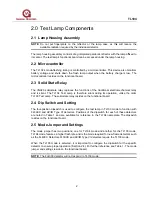
2.1 Lamp Housing Assembly 

NOTE:

 Do not put fingerprints on the reflector or the lamp case, as this will reduce the 

available radiation required by the individual detector. 

The lamp housing assembly consists of a gold-plated parabolic reflector with the lamp affixed to 
its center. The test lamp’s functional board can be accessed under the lamp housing. 

2.2 Microcontroller 

The TL104’s mode-flashing timing is controlled by a microcontroller. This device also monitors 
battery voltage and shuts down the flash lamp output when the battery charge is low. The 
microcontroller resides on the functional board. 

2.3  Solid State Relay  

The VN920 solid-state relay replaces the functions of the traditional electromechanical relay 
and is silent. The TL104 Test Lamp is therefore silent during its operation, unlike the older 
TL103 Test Lamp. The solid-state relay resides on the functional board. 

2.4  Dip Switch and Setting 

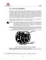
The four-position dipswitch is used to configure the test lamp in TL103 mode to function with 
FL3XXX and UV/IR Type VI detectors. Positions of the dipswitch for each of these detectors 
are noted in Table 1 and are available for reference in the TL104 nameplate. The dipswitch 
resides on the functional board. 

2.5  Mode Jumper and Settings 

The mode jumper has two positions, one for TL104 mode and another for the TL103 mode. 
TL104 mode features a higher flash rate and is the mode required for new flame detectors such 
as the FL4000. Detectors FL3XXX and UV/IR Type VI detectors require the TL103 mode. 

When the TL103 mode is selected, it is important to configure the dipswitch for the specific 
detector to ensure proper operation (Section 2.4). For further reference see Table 1. The mode 
jumper and settings reside on the functional board. 

NOTE:

  The FL4000 detector will not respond to TL103 mode. 

Содержание TL104

Страница 1: ...ment may be used and disseminated only for the purposes and to the extent specifically authorized in writing by General Monitors Instruction Manual 10 05 General Monitors reserves the right to change published specifications and designs without prior notice MANTL104 Part No MANTL104 Revision B 10 05 ...

Страница 2: ...TL104 This page is intentionally left blank ii ...

Страница 3: ... 2 Microcontroller 2 2 3 Solid State Relay 2 2 4 Dip Switch and Setting 2 2 5 Mode Jumper and Settings 2 2 6 Lead Acid Rechargeable Battery 3 2 7 Recharge Jack and Cap 3 2 8 Test Lamp Momentary Contact Button 3 2 9 Red Aluminum Case and Gray Cap 3 3 0 USE AND OPERATION 4 4 0 TEST LAMP MAINTENANCE AND WARRANTY 6 4 1 Maintenance 6 4 2 Warranty 6 5 0 TROUBLESHOOTING GUIDE 7 6 0 CUSTOMER SUPPORT 8 6 1...

Страница 4: ...Notes Cautions and Warnings NOTE Notes provide supplementary details such as exception conditions alternate methods for a task time saving tips and references to related information CAUTION These notices describe precautions to prevent hazardous conditions that may damage the equipment WARNING These notices describe precautions to prevent hazardous conditions that may cause injury to people workin...

Страница 5: ...pectra to activate UV and or IR detectors To simulate the flickering of a fire the test lamp automatically flashes at various selectable rates The TL104 is designed for use in Class I Division 1 2 Groups C and D areas The test lamp functions on internal lead acid batteries which when fully charged allows continuous operation for 20 to 30 minutes An internal circuit prevents operation when the batt...

Страница 6: ... operation unlike the older TL103 Test Lamp The solid state relay resides on the functional board 2 4 Dip Switch and Setting The four position dipswitch is used to configure the test lamp in TL103 mode to function with FL3XXX and UV IR Type VI detectors Positions of the dipswitch for each of these detectors are noted in Table 1 and are available for reference in the TL104 nameplate The dipswitch r...

Страница 7: ...harge Jack and Cap The recharge jack is located directly under the aluminum single slotted cap and can be accessed when the aluminum cap is removed The battery charger is connected to the recharge jack When this is done and the battery charger is connected to 120 AC power line the battery will be recharged 2 8 Test Lamp Momentary Contact Button The test lamp momentary contact button is the red but...

Страница 8: ...Table 1 and Figure 1 to assure that dipswitch settings and mode jumper position are correct for the particular detector CAUTION When operating in conditions involving fog rain or frost UV and IR radiation are diminished with increasing levels of moisture The moisture level will affect the potential range of the detector When using the test lamp in conditions of frost make sure that the lens is fre...

Страница 9: ...de FL3002 TL103 10 FL3002 triggers into alarm mode FL3100 TL103 20 FL3100 triggers into alarm mode FL3101 TL103 35 FL3101 triggers into alarm mode FL3102 TL103 10 FL3102 triggers into alarm mode FL3110 TL103 20 FL3110 triggers into alarm mode FL3111 TL103 35 FL3111 triggers into alarm mode FL3112 TL103 8 FL3112 triggers into alarm mode FL4000 TL104 Any dipswitch setting 30 FL4000 enters test mode ...

Страница 10: ...fective or damaged equipment will be made by General Monitors personnel Defective or damaged equipment must be shipped prepaid to General Monitors or the representative from which shipment was made In all cases this warranty is limited to the cost of the equipment supplied by General Monitors The customer will assume all liability for the misuse of this equipment by its employees or other personne...

Страница 11: ...the problem Condition Possible Solution Test Lamp does not flash Battery may require a recharge Check Table 1 Verify that dipswitch settings are set as specified in Table 1 Test Lamp flashes but is unable to trigger detector Verify Mode Jumper is set according to Figure 1 Test Lamp does not flash and battery has been recharged for 14 hours Lamp filament may be broken Check power and lamp connector...

Страница 12: ... uk IRELAND Ballybrit Business Park Galway Republic of Ireland Phone 353 91 751175 Fax 353 91 751317 Email info gmil ie SINGAPORE No 2 Kallang Pudding Rd 09 16 Mactech Building Singapore 349307 Phone 65 6 748 3488 Fax 65 6 748 1911 Email genmon gmpacifica com sg MIDDLE EAST LOB12 G20 P O Box 61209 Jebel Ali Dubai United Arab Emirates Phone 971 4 8815751 Fax 971 4 8817927 Email gmme emirates net ae...

Страница 13: ...ange 0 to 90 3 RH non condensing Weight 7 9 lb about 3 5 kg Dimensions 13 L x 5 D 330 mm L x 127 mm D Approvals CSA CE Marking Charging time 14 hours minimum Output spectra Broadband emissions in UV visible and IR Charger input 115 V 10 50 60 Hz Output 12 1 VDC 250 mA Detection Range See Table 1 for maximum distance per flame detector model 9 ...

Отзывы: