background image

ENGLISH

9

170130

3. Attach the rubber foot pads onto the feet of the saw base.

HOLD-DOWN CLAMP ASSEMBLY:

1. The hold down clamp included can be installed in either of the two holes 

positioned just behind the fence at both the left and right ends.

2. Slide the shaft into the hole and then tighten the hold-down clamp 

retention screw (B, fig.1 & 2). Grooves around the shaft allow the screw 

to hold the shaft from moving vertically while allowing it to rotate for 

easy clamp positioning.  

•  You can adjust the height and position of the clamping arm according 

to the thickness and shape of the workpiece with the knob at the 

back top. 

•  Place the workpiece on the table tightly against the fence and slide it 

to the desired cutting position. 

• 

Tighten the hold-down clamp fine height adjustment knob (D, fig.1 & 

2) to secure the workpiece.

LASER

1. 

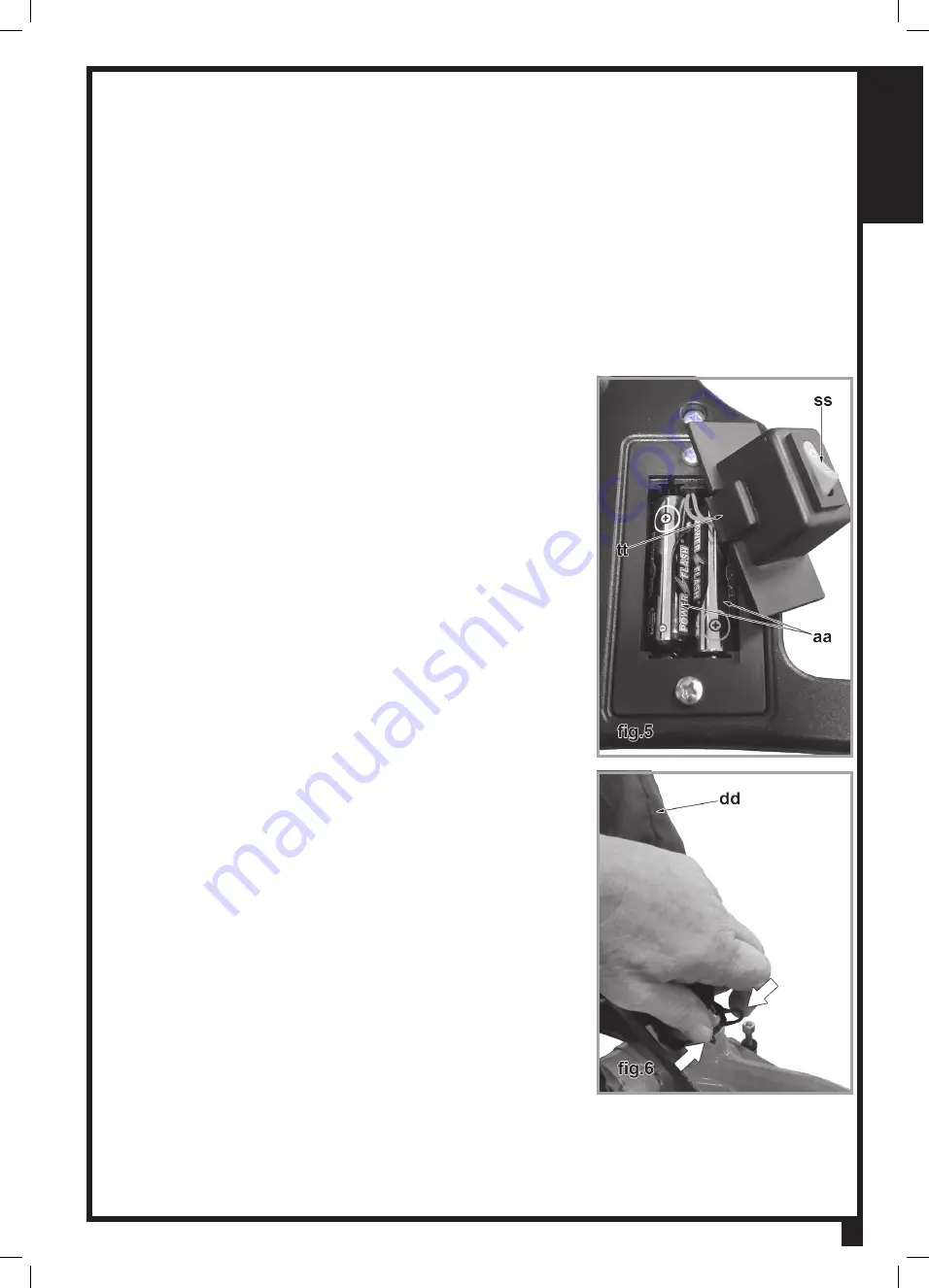
Locate the red laser switch (ss, fig.5) on the top surface of the handle 

assembly, to the right of the carry handle. 

2. 

Press in the retention tab (tt, fig.5) and lift the switch/cover off the laser 

battery compartment. 

3. Insert the 2 AA batteries into the compartment as shown. 
4. 

Re-install the switch/cover.

SAWDUST COLLECTION

You can operate this machine more safely and conveniently with a dust 

collector.

1. Connect a dust collection system hose (not included) to the dust 

collection port nozzle on the back of the metal guard (J, fig.1).

2. If a dust collector is not available or convenient, use the included dust 

bag


and fit it to the dust collection port at the back of the guard.

3. 

Attach the dust bag (dd, fig.6) over the dust port by squeezing the 

springs in the bag’s opening.

4. Whenever the dustbag is half full, remove it and zip open the bag at the 

bottom. Clean out the sawdust completely.


Be sure all screws are fastened, and all adjusting keys and wrenches 

are removed.

Содержание MS3003

Страница 1: ...tal D Handle Bevel cuts up to 45 degrees left Miter cuts up to 45 degrees left and right 10 in saw blade with carbide tipped teeth Powerful 15 A motor With Adjustable cut depth for dadoes Shaft lock f...

Страница 2: ...International reserves the right to make changes to components parts or features of this unit as deemed necessary without prior notice and without obligation to install any such changes on previously...

Страница 3: ...e THE WARNINGS CAUTIONS AND INSTRUCTIONS discussed in this instruction manual cannot cover all possible conditions or situations that could occur It must be understood by the operator that common sens...

Страница 4: ...ver carry your bench tool by the cord or pull on the cord to unplug it Protect the cord from potential sources of damage heat oil solvents sharp edges or moving parts Replace damaged cords immediately...

Страница 5: ...ol repaired before using it 21 DISCONNNECT THE PLUG FROM POWER BEFORE MAKING ANY ADJUSTMENTS Changing attachments or accessories can be dangerous if the tool could accidentally start 22 STAY ALERT Wat...

Страница 6: ...nd 650 nm wavelengths AVOID DIRECT EYE EXPOSURE 3 The laser must be used and maintained in accordance with the manufacturer s instructions Never aim the beam at any person or an object other than the...

Страница 7: ...zer bar D Hold down clamp fine height adjustment E Hold down clamp coarse height adjustment F Saw bevel locking lever G Saw bevel angle indicator H Laser aperture I Saw head lock knob J Dust port K Bl...

Страница 8: ...ton out Ensure the table lateral extensions rear stabilizer hold down clamp and dust bag are properly attached TABLE EXTENSIONS Two table side extensions A T fig 1 2 are included with your saw to help...

Страница 9: ...o secure the workpiece LASER 1 Locate the red laser switch ss fig 5 on the top surface of the handle assembly to the right of the carry handle 2 Press in the retention tab tt fig 5 and lift the switch...

Страница 10: ...ructions attaching the machine to the workbench and checking that all attachments are correctly installed you can use your saw WARNING Be sure to wear appropriate protective equipment For your safety...

Страница 11: ...u have finished cutting release the trigger switch and wait until the saw blade stops completely then raise the handle This is a good setting for simple angle cuts COMPOUND CUT 1 Loosen the miter angl...

Страница 12: ...h the desired depth of the dado 5 Tighten the knurled locking nut kk fig 7 8 on the shank of the dado depth adjustment screw to lock its setting 6 Test the depth of the dado by making a trial cut in a...

Страница 13: ...ause of sharpening adjust the machine per the following instructions 1 Push the handle down completely to its lowest position 2 Turn the kerf depth adjustment screw cc fig 12 with a 5 mm hex wrench so...

Страница 14: ...E 1 At the rear of the saw on the right side of where the arm pivots is a hex socket head depth setting screw that limits the 45 bevel 2 Loosen the locking nut and adjust the screw with a 5 mm hex key...

Страница 15: ...slot and catching in the blade If the tool is to be stored for any length of time remove the batteries from the laser battery compartment to prevent damage to the device Lubrication is done at the fac...

Страница 16: ...ENGLISH 16...

Страница 17: ...biseau jusqu a 45 degr s gauche Coupes d onglet jusqu a 45 degr s gauche et droite Lame de scie de 10 po pointes au carbure Moteur puissant de 15 amp res Avec R glage de coupe pour engravure Facilit d...

Страница 18: ...tie CLAUSE DE NON RESPONSABILIT L information et les caract ristiques pr sent es dans ce manuel se rapportent la machine telle qu elle est sortie de l usine au moment de mettre sous presse En raison d...

Страница 19: ...ements de s curit les pr cautions l assemblage le fonctionnement les proc dures d entretien la liste des pi ces et les sch mas des pi ces Gardez votre facture avec ces instructions crivez votre num ro...

Страница 20: ...NE PARTIE M TALLIQUE DE L OUTIL durant son usage Toujours tenir l outil par la poign e en plastique pour pr venir les chocs lectriques en cas de contact avec un fil sous tension 6 NE PAS ABUSER LE COR...

Страница 21: ...le et de graisse 18 VITEZ LA MISE EN MARCHE ACCIDENTELLE Assurez vous que l interrupteur est la position ARR T avant de brancher l outil 19 TOUJOURS V RIFIEZ ET RETIREZ LES CL S DE R GLAGE ET LES CL S...

Страница 22: ...CONTACT AVEC LE MAT RIAU COUPER Le mouvement de la lame peut faire sauter la scie brusquement et pourrait causer des blessures SI VOUS EFFECTUEZ UNE COUPE UTILISANT QU UNE SEULE MAIN ASSUREZ VOUS QUE...

Страница 23: ...ES DE LA BO TE Votre scie onglets combin e coulisse est compl tement assembl e dans la bo te sauf quelques petits accessoires V rifiez si tout ce dont vous avez besoin est inclus 3 Extensions un pour...

Страница 24: ...de biseau H Guide laser I Bouton de verouillage de la t te J Conduite poussi rres K Levier de relevage pour prot ge lame L Poign e de transport M Poign e en D horizontale N D clencheur O Couvercle vi...

Страница 25: ...sateur arri re est gliss avec l extr mit recourb e vers le bas dans les trous l arri re de la base de la table Il doit tre fix en place par une vis hexagonale de 4 mm sur la face inf rieure de la base...

Страница 26: ...nt le ressort dans l ouverture du sac 4 chaque fois que le sac sera moiti rempli de bran de scie retirez le et ouvrez sa fermeture clair du fond Videz compl tement le bran de scie Assurez vous que tou...

Страница 27: ...surface sup rieur de la poign e droite de la poign e de transport M fig 1 et 2 4 La scie tant en position lev e le garde lame Q fig 1 2 compl tement descendu appuyez sur la g chette N fig 1 2 dans la...

Страница 28: ...linez la sur la gauche entre 0 et 45 en vous r f rant l chelle de biseau V fig 1 et 2 et puis verrouillez la l angle d sir 4 Faites d marrer la scie et attendez qu elle atteigne sa vitesse maximale 5...

Страница 29: ...ntes la profondeur r gl e ou faites une coupe de chaque c t et retirez manuellement le mat riau entre celles ci ENTRETIEN ENL VEMENT ET REMONTAGE DE LA LAME AVERTISSEMENT D branchez toujours l outil a...

Страница 30: ...de verrouillage hexagonal nn fig 12 sur la tige du boulon de r glage de profondeur de trait de scie pour bloquer votre r glage REMPLACEMENT DES BROSSES DE CHARBON AVERTISSEMENT Avant de faire toute i...

Страница 31: ...condition en adoptant un programme d entretien r gulier AVERTISSEMENT Avant d inspecter ou d entretenir la scie teignez la et d branchez la fiche de l alimentation Avant chaque utilisation examinez l...

Страница 32: ...nel d un centre de service autoris devrait effectuer des r parations modifications ou entretien n cessitant le d montage de la scie Tout dommage l outil devrait tre corrig dans un centre de r paration...

Отзывы: