


MS3002 Manual v.200909
Page 36
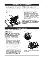
(3), release the positive stop lock
lever (2) and tighten the miter handle
(1). The table is now locked at the
desired angle. Positive stops are
provided at 0°, 15°, 22.5°, 31.6° and
45°.
IMPORTANT
: Always tighten the miter
table lock handle before performing every
cutting operation.
5. Turn the Laser Tracking on and
position the workpiece on the table
for prealignment of your cut.
BEVEL CUT
(FIG. CC)
1. When a bevel cut is required, loosen
the bevel lock handle (1) by turning it
clockwise.
2. Tilt the cutting head to the desired
angle, as shown on the bevel scale
(2).
3. The blade can be positioned at any
angle, from a 90° straight cut (0° on
the scale) to a 47° left bevel. Tighten
the bevel lock handle (1) to lock the
cutting head in position. Positive
stops are provided at 0° and 45°.
4. Turn the Laser Trac
®
on and position
the workpiece on the table for
prealignment of your cut.
1
2
3
Fig. BB
COMPOUND CUT
(FIG. CC, DD)
A compound cut is the combination of a
miter and a bevel cut simultaneously.
1. Loosen the bevel lock handle (1)
and position the cutting head at the
desired bevel position. Lock the
bevel lock handle (1). (Fig. CC)
2. Loosen the miter handle (3). Lift up
the positive stop lock lever (4) and
position the table at the desired
angle. Release the positive stop lock
lever (4) and lock the miter handle
(3). (Fig. DD)
F . CC
ig
1
2
OPERATION
Содержание MS3002
Страница 50: ...MS3002 Manual v 200909 Page 50 EXPLODED DIAGRAM ...
Страница 51: ...MS3002 Manual v 200909 Page 51 ...
Страница 52: ...MS3002 Manual v 200909 Page 52 ...